Open topic with navigation

How to define the 3D Dimension - style, insert, edit
Define the Dimension style in the project and insert some dimensions on the structure according to the predefined style.
Definition of the Dimension style
- Open the attached project "Dim.esa". There are 2D plates, 1D members and openings.
- Check if snapping point type “End points” is active.
- Find “Dimension style manager” tool in Libraries. This manager specifies Dimension styles which can be used in the project.
- Open the dialogue and create a New style.
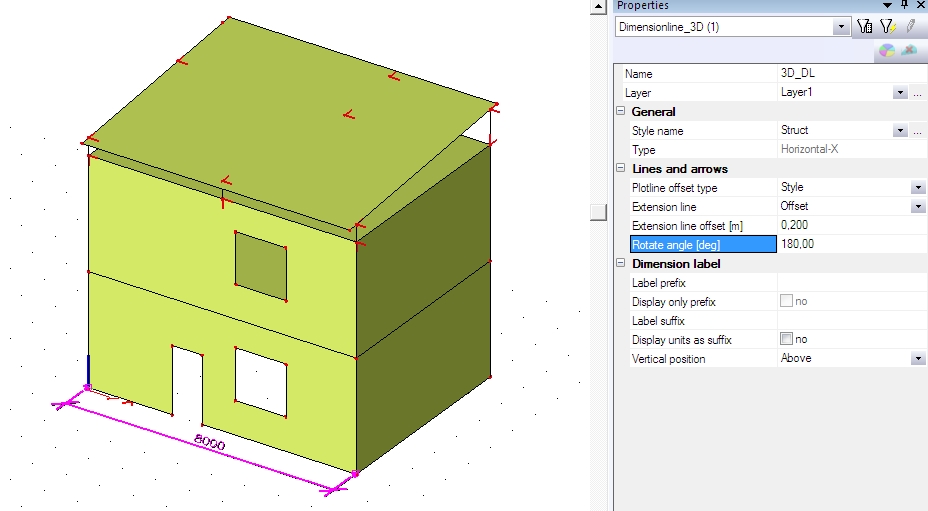
- Define the name of the style as “Struct” and fill the rest properties according to the picture.
The description of the dimension line:
Inserting the Dimension line to the project:
- Find dimensions in the service Structure->Modelling/Drawing->Dimension Tools or on toolbar Dimension tools.
- Select the Linear type of dimension for the X direction.
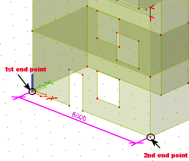
- Select two end points on the structure (using snapping mode) - the bottom of the front wall - and end the command (ESC).
- Rotate the dimension line to be visible in front of the wall.
- Insert the dimensions also in the Y and Z direction in the same way. Use the proper Dimension tools – the one with little Y and little Z .
- Define one more Dimension style for openings - "Open". Fill the new style according to the picture.
- Use the dimension in the Z direction and create continuous dimension line (the command wont be finished by ESC after the first dimension is created). The new dimension starts on bottom of the wall and it shows distances between windows on the front wall. Change the dimension style in properties before the first point is set – “Open”.
Order of selected end points is shown on the picture. Select 6 points. The first and the last one is on the edge of the wall and the rest is on opening’s corners.
Edit the Dimension line:
- Select the continuous dimension line on the edge of the wall. Properties are displayed in the Property dialogue. Check the selected dimension style – “Open”. The Plotline offset can be defined by “Style” (in our example – Open) or as “User defined”.
- Change the Plotline offset type to “User defined” and check the changes in the model and in properties. There is a new row in properties.Define a new plotline offset by number in this new row.
- The plotline offset is now defined by value in properties and not by definition in the Dimension style “Open”. Change some more properties according to the picture.
Extension line type “Offset” - define the distance from the inserting point.
Extension line type “Length” - define the length of the extension line.
The final project with Dimension lines and changed properties is in attached "final_Dim.esa".
Open topic with navigation