![]()
|
||
|
|
||
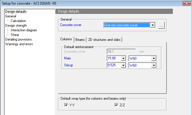
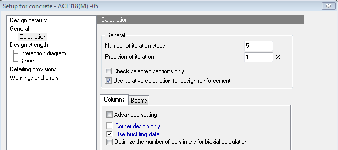
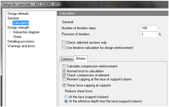
This setup is available from tree Concrete > 1D member > Setup. After clicking on this item the dialog in the picture below is opened
The global setting is divided to the following sheets:
Blue coloured parameters might be changed for each member by using local setting (Member data).
Concrete setup can be opened too via action button Concrete setup or via Code setup in the single check
|
Action button Concrete setup |
Button Code setup in the single check |
|
|
|
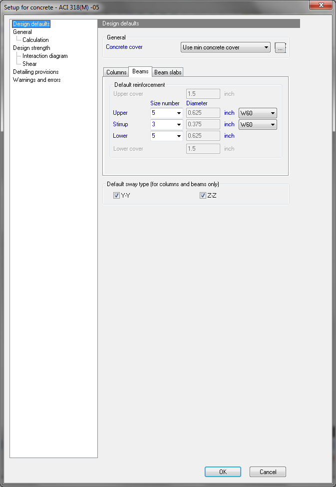
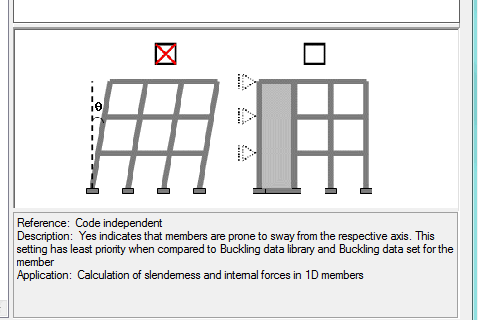
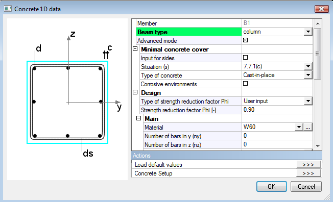
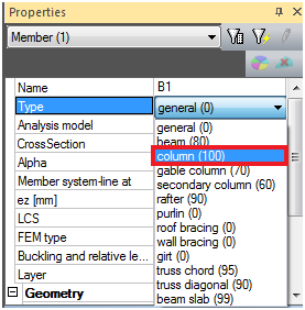
This group is divided into three main parts. It is possible to define minimal concrete cover, set default values for member design, such as reinforcement diameters, and materials both independent for main reinforcement and stirrups. It is also possible to define sway type here.
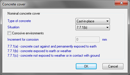
User may choose from two possibilities to determine concrete cover:
By selecting this possibility, program will enable edit boxes for concrete cover, both for upper and lower surface, and user defines his own value to be used.
By this possibility, user let SCIA Engineer to evaluate minimum concrete cover, which may be used according to the Code. Parameters used for this evaluation may be defined in Concrete cover dialog, which is shown below. Here user may redefine type of concrete cover, situation and some more addition to the value due to the corrosive environments.
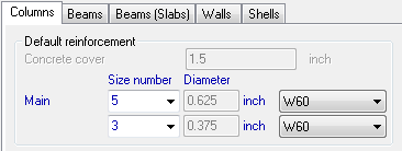
Default value of reinforcement and stirrup diameters together with default material used are to be defined here. User may define default settings separately for beams, columns and beam slabs members, in each of three folders. Design defaults for Beams are shown on the first picture of this chapter. In 2D concrete setup dialog, different folders will be displayed. They are named Plates, Walls and Shells. Values from Plates folder are the similar to those, which are stored in Beam slabs folder in 1D concrete setup.
This is option for calculation of slenderness and internal forces in 1D members. If the check box is active, it indicates that members are prone to sway from the respective axis. This setting has least priority when compared to Buckling data library and Buckling data set for the member.
Here user may check or even adjust important design material characteristics of concrete and non-prestressed reinforcement steel.
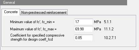
The value sets minimum value of compression strength of concrete. According to the Code, concrete shall be proportioned to provide an average compressive strength, fcr and shall satisfy the durability criteria. For concrete designed and constructed in accordance with the Code, fc′ shall not be less than 17 Mpa = 2500 psi.
The value sets maximum value of compression strength of concrete. Because of a lack of test data and practical experience with concretes having compressive strengths greater than 70 MPa, the Code imposed a maximum value of 8.3 MPa on √fc’ for use in the calculation of shear strength of concrete beams, joists, and slabs. Exceptions to this limit were permitted in 11.1.2.1.
This coefficient reduces concrete compression strength. According to the Code, concrete stress of 0.85fc′ shall be assumed uniformly distributed over an equivalent compression zone bounded by edges of the cross section and a straight line located parallel to the neutral axis.
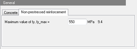
Here the maximum design strength of non-prestressed reinforcement is defined. Code defines maximum of the values of fy and fyt , used in design calculations, shall not exceed 550 MPa, except for prestressing steel and for spiral transverse reinforcement in 10.9.3.
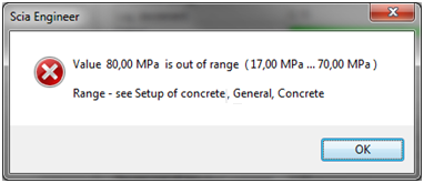
Minimum and maximum value of fc’ together with maximum value of fy are also limit values for concrete and reinforcement steel material parameters. It is not possible to input appropriate values in material properties. If so, en error message will be displayed.
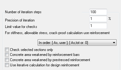
The user can set general parameters for calculation of 1D member and special parameters for calculation and design reinforcement for beams and column.
There is possible to define parameters, which will be used for beams and columns
|
Group |
General > Calculation |
|
Type of parameter |
Edit box |
|
Default: |
100 (Limit values from 1 to1000) |
|
Local setting |
NO |
|
Influence |
All iterative calculation in concrete design |
This setting is used for iterative calculation in concrete. If iterative calculation does not finish after reaching number of steps, the calculation is finished. In this case, the result will not be presented and user has to make some changes in calculated structures or decrease precision of iteration (see chapter "4.1 Concrete setup for 1D member") or increase number of iteration steps.
|
Group |
General > Calculation |
|
Type of parameter |
Edit box |
|
Default: |
1% (Limit values from 0.0001 to10) |
|
Local setting |
NO |
|
Influence |
All iterative calculation in concrete design |
This setting is used for iterative calculation in concrete. Iterative calculation is finished if difference of results of two consecutive iteration steps is lesser than this precision. If iterative calculation does not finish after reaching number of steps, the calculation is finished. In this case, the result will not be presented and user has to:
|
Group |
General > Calculation |
|
Type of parameter |
Check box |
|
Default: |
OFF |
|
Local setting |
NO |
|
Influence |
All results in concrete with exception of service Concrete slenderness |
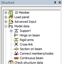
If this check box is ON, then the results are calculated and presented only at the ends of the member and in user defined sections. It follows, that calculation is much faster. The user sections can be defined in tree Structure > Model data > Section on beam
There is comparison of results if this setting is ON/OFF and some user sections are defined (in thirds of member length)
|
Check selected section only is OFF
|
|
|
Check selected section only is ON and user section are defined
|
|
|
Group |
General > Calculation |
|
Type of parameter |
Check box |
|
Default: |
OFF |
|
Local setting |
NO |
|
Influence |
Design reinforcement for 1D member |
Design strength of the structure is calculated multiplying the nominal strength by a strength reduction factor φ. This factor depends on the strain in tensile reinforcement, but this strain is unknown before design reinforcement. It follows, that for calculation of this value:
If this check box Use iterative calculation for design of reinforcement is OFF, then strength reduction factor loaded from concrete setup (see chapters ) will be used. It means that:
Else if this check box is ON, then iterative calculation for strength reduction factor will be used for design reinforcement to beam ("8.2 Design of reinforcement for 1D members (beams, beams as slab, columns)") and for column ("8.2 Design of reinforcement for 1D members (beams, beams as slab, columns)")
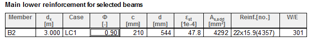
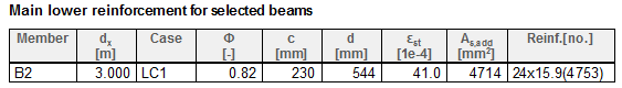
There is comparison of results if this setting is ON/OFF for simply supported beam.
|
Check box =OFF |
|
|
Check box =ON |
|
If concrete member data are defined on the member and Type of strength reduction factor Phi = User input, then this check box has not influence to calculation strength reduction factor , because strength reduction factor is directly loaded from concrete member data
|
Group |
General > Calculation > tab-sheet Columns |
|
Type of parameter |
Check box |
|
Default: |
OFF |
|
Local setting |
NO |
|
Influence |
Design reinforcement for columns |
If this check box is ON, there are only basic parameters in tab-sheet Column , which can be edit. After switching ON this check box Advanced setting, there are much more parameters for setting calculation of the columns.
|
Group |
General > Calculation > tab-sheet Columns |
|
Type of parameter |
Check box |
|
Default: |
OFF |
|
Local setting |
NO |
|
Influence |
Design reinforcement for columns |
Corner design only is special type of calculation, where the reinforcement is designed only in corner of cross-section with internal angle 90 deg. It is an iterative calculation, where number of bars is same, but the diameter of bars increases. This parameter has influence only for basic concrete cross-section, see table below.
|
Section |
Rectangular section |
I section |
T section |
L section with lower flange |
L section with upper flange |
|
Number of bars |
4 |
8 |
6 |
5 |
5 |
|
Shape |
|
|
|
|
|
This type of calculation is supported only for basic concrete cross-section (see chapter "8.2 Design of reinforcement for 1D members (beams, beams as slab, columns)"), for other type of cross-section calculation finished with error 683 (The design of main reinforcement area for the column is not supported for this type of cross-section)
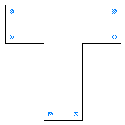
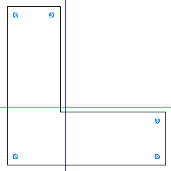
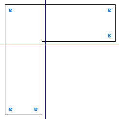
There is comparison of design reinforcement with using method Only corner design for rectangular column with different value of internal forces.
|
Group |
General > Calculation > tab-sheet Columns |
|
Type of parameter |
Check box |
|
Mode: |
Basic mode |
|
Default: |
ON |
|
Local setting |
YES |
|
Influence |
Internal forces and design reinforcement to column |
This setting allows taking into account second order eccentricity (magnified moments calculated according to clause 10.12 and 10.13 in ACI 315-05, see chapter "7.2 Internal forces for 1D members (beam, beam as slab, column)". The second order eccentricity in direction of local axis will be taken into account only if slenderness of the column in this direction is greater than limit slenderness and this check box is ON.
The detailed information about calculation of these magnified moments are presented in numerical output in the service Internal forces (tree Concrete >1D member), if the value My,recalc or Mz, recalc is selected.
|
Group |
General > Calculation > tab-sheet Columns |
|
Type of parameter |
Check box |
|
Mode: |
Basic mode |
|
Default: |
ON |
|
Local setting |
NO |
|
Influence |
Only design reinforcement to column with rectangular section |
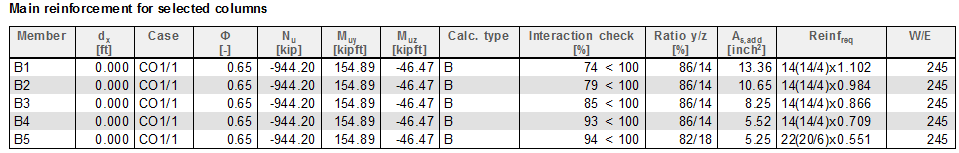
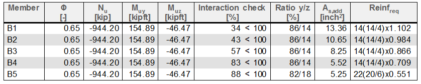
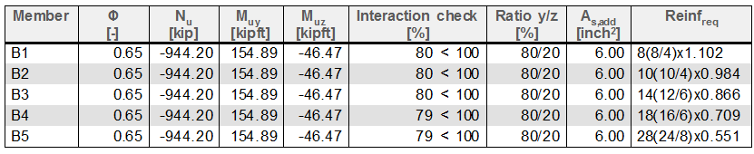
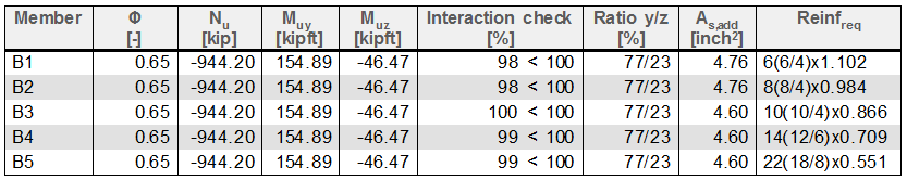
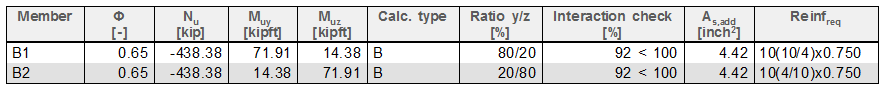
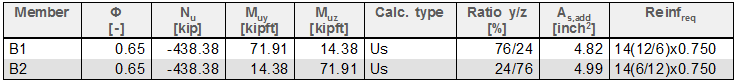
The design reinforcement with using biaxial methods depends on value Ratio y/z (ratio of reinforcement in direction of y and z of LCS),see chapter . If this check box is ON, then the biaxial method is independent on value Ratio y/z and program tries to find the best arrangement of bars in cross-section with the minimum number of bars. It is iterative calculation, where program checked all possible arrangements of bars of reinforcement according to interaction formula ( see chapter "4.1 Concrete setup for 1D member") and select this one, which result of interaction formula is the nearest to one.
This setting has influence to speed of calculation, because if the check box is ON, iterative calculation is used and therefore the speed of calculation is slower, but the result of design in many cases is better, see table below.
There is comparison of results if this setting is ON/OFF for column with the same load, but with different size of diameter of longitudinal reinforcement.
|
Check box Optimize…is OFF |
|
|
Check box Optimize…is ON |
|
|
Group |
General > Calculation > tab-sheet Columns |
|
Type of parameter |
Edit box |
|
Mode: |
Advanced mode only |
|
Default: |
2% (Limit values from 0 to10) |
|
Local setting |
yes |
|
Influence |
Only design reinforcement |
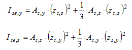
There are some values in design of reinforcement, which are dependent on area of reinforcement, for example:
These values should be calculated before design of reinforcement, but before design we do not know area of reinforcement. It follows that for calculation of this value
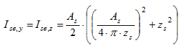
The third solution is implemented in SEN via edit box User estimate of reinf. for design of reinforcement, where user can set ratio of reinforcement, which will be used for calculation of the values above. The calculation moment of inertia of reinforcement depends on type of method and shape of concrete cross-section too. There are the following methods for calculation the radius of gyration of the total reinforcement:
As = Ratiolon ⋅Ac
A1si = As/ns
As = Ratiolon ⋅Ac
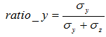 ,
, 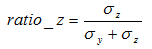
if σy = 0 MPa and σz = 0 MPa , then ratio_y = ratio_z = 0,5
As,y(z) = ratio_y(z)⋅As
As = Ratiolon ⋅Ac
|
where |
|
|
Ratiolon |
is reinforcement ratio loaded from concrete setup |
|
Ac |
is cross sectional area of concrete |
|
ns |
is number of bars in cross-section (the number of bars for Only corner design depends on shape of cross-section, see chapter "8.2 Design of reinforcement for 1D members (beams, beams as slab, columns)") |
|
A1si |
is the cross-sectional area of i-th bar of reinforcement |
|
zs,y(z)i |
is the position of i-th bar of reinforcement from centroid of concrete cross-section in direction of y(z) axis of LCS (the positions of bars for Only corner design depends on shape of cross-section, see chapter "8.2 Design of reinforcement for 1D members (beams, beams as slab, columns)""4.1 Concrete setup for 1D member") |
|
σy(z) |
is the bending stress in concrete calculated for uncracked concrete cross-section according to formulas: |
|
Mu,y(z) |
is the 1st order factored moment around of y (z) axis of LCS (in SEN value My(z)) |
|
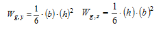
Wg,y(z) |
is the section modulus of concrete cross-section around y (z) axis of LCS
|
|
zs,y(z) |
is the position of reinforcement from centroid of concrete cross-section in direction of y (z) axis for rectangular section (the positions of bars for Only corner design depends on shape of cross-section, see chapter "4.1 Concrete setup for 1D member") zs,y = 0,5⋅b- (c + dss + 0,5⋅ds), zs,z = 0,5⋅h- (c + dss + 0,5⋅ds) |
|
zs |
is th position of reinforcement from centroid of concrete cross- for circular section zs = 0,5⋅D- (c + dss + 0,5⋅ds), |
|
b |
is width of rectangular cross-section |
|
h |
is height of the rectangular cross-section |
|
D |
is diameter of circular cross-section |
|
cnom |
is nominal concrete cover loaded from concrete setup (Design default) or from concrete member data, if member data are defined on calculated column |
|
ds |
is diameter of longitudinal reinforcement loaded from concrete setup (Design default) or from concrete member data, if member data are defined on calculated column |
|
dss |
is diameter of transverse reinforcement (stirrup) loaded from concrete setup (Design default) or from concrete member data, if member data are defined on calculated column |
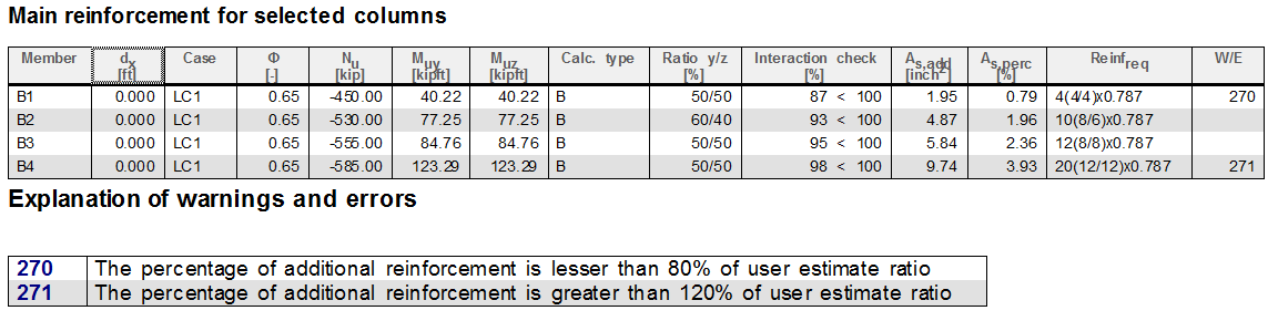
If required designed area is lesser than 80% of estimated area setting in concrete setup or concrete member data and Equation for calculation EI for critical load Pc = 10-11(see chapter ), program gives warning 270 (The percentage of additional reinforcement is lesser than 80% of user estimate ratio). In this case, the value of user estimate ratio in concrete setup (if member data is not defined) or in concrete member data (if it is defined) should be decreased.
If required designed area is greater than 120% of estimated area setting in concrete setup or concrete member data and Equation for calculation EI for critical load Pc = 10-11(see chapter ), program gives warning 271 (The percentage of additional reinforcement is greater than 120% of user estimate ratio). In this case, the value of user estimate ratio in concrete setup (if member data is not defined) or in concrete member data (if it is defined) should be increased.
There is design of reinforcement for rectangular columns with different load and with different area of reinforcement column with.
|
Group |
General > Calculation > tab-sheet Columns |
|
Type of parameter |
Radio buttons |
|
Mode: |
Advanced mode only |
|
Default: |
Automatic determination |
|
Local setting |
YES |
|
Influence |
Only design reinforcement to column with rectangular section |
There are supported only following cross-section for design reinforcement to column in SEN:
Type of method can be selected by user via radio buttons, see picture below
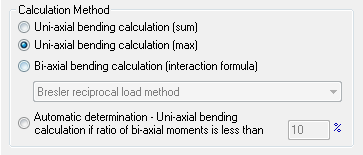
If Calculation Method = Automatic determination, then user can input limit ratio of bending moments, when the biaxial calculation will, be used, see chapter "4.1 Concrete setup for 1D member"
If Calculation Method = Biaxial bending calculation (interaction formula), then user can select type of biaxial method , which will be used for design of reinforcement, see chapter "4.1 Concrete setup for 1D member"
4.1.3.1.5.6.1 Uniaxial bending calculation if ratio of biaxial moments is less than
|
Group |
General > Calculation > tab-sheet Columns |
|
Type of parameter |
Edit box |
|
Mode: |
Advanced mode only |
|
Default: |
10% (Limit values from 0 to100) |
|
Local setting |
YES |
|
Influence |
Only design reinforcement to column with rectangular section and with Calculation method = Automatic determination |
Type of method, which will be used for design reinforcement, if Calculation Method =Automatic determination is selected, depends on ratio bending moments.
Ratio(My/Mz) = 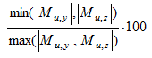
|
where |
|
|
Mu,y |
is factored (magnified) value of the bending moment around y –axis (including second order effect) |
|
Mu,z |
is factored (magnified) value of the bending moment around z –axis (including second order effect) |
If this ratio is lesser than limit value set in this edit box, then for design of reinforcement in the section of the column Uniaxial bending calculation (max) will be used. Otherwise the Biaxial bending calculation will be used for design of reinforcement
This edit box is active only in the case, if in the combo box Type of calculation method item Automatic determination is selected
There is comparison of results for automatic determination type of method for design of reinforcement for column with different value of bending moment.
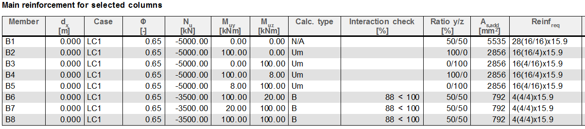
If bending moments in both direction are zero, then reinforcement is designed only for normal force and calculation type =N/A
4.1.3.1.5.6.2 Type of biaxial method
|
Group |
General > Calculation > tab-sheet Columns |
|
Type of parameter |
Combo box |
|
Mode: |
Advanced mode only |
|
Default: |
Bressler reciprocal load method |
|
Local setting |
YES |
|
Influence |
Only design reinforcement to column with rectangular section and with Calculation method = Biaxial or Automatic determination |
Biaxial method is iterative calculation, where the bars of reinforcement are added to cross-section depending on ratio y/z (see chapter "4.1 Concrete setup for 1D member") or number of bars is optimized (see chapter "4.1 Concrete setup for 1D member") as long as interaction formula is not fulfilled.
There are supported three types of method for biaxial calculation:
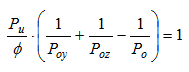
|
where |
|
|
Pu |
factored axial force |
|
Poy |
Maximum uniaxial resistance of the column with a moment of Muy, it means axial resistance for bending moment Muy. It is intersection of interaction diagram and vertical line ( parallel with axis P) across the point with coordinate [Pu,Muy,0] |
|
Poz |
Maximum uniaxial resistance of the column with a moment of Muz, it means axial resistance for bending moment Muz. It is intersection of interaction diagram and vertical line ( parallel with axis P) across the point with coordinate [Pu,0, Muz] |
|
Po |
Maximum axial resistance without bending moments. It is intersection of interaction diagram and vertical line ( parallel with axis P) across the point with coordinate [Pu,0, 0] |
|
Muy(z) |
Factored (magnified) moment at section about the y (z) axis of LCS of the member |
|
f |
Strength reduction factor calculated by iterative calculation, loaded from concrete setup or from concrete member data, see chapter "4.1 Concrete setup for 1D member" |
|
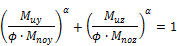
where |
|
|
Muy(z) |
Factored (magnified) moment at section about the y (z) axis of LCS of the member |
|
Mnoy(z) |
nominal uniaxial moment resistance about the y (z) axis of LCS of the member |
|
f |
Strength reduction factor calculated by iterative calculation, loaded from concrete setup or from concrete member data, see chapter "4.1 Concrete setup for 1D member" |
|
α |
Exponent of interaction formula, which can be set in concrete setup, "4.1 Concrete setup for 1D member" |

|
where |
|
|
b |
Exponent of interaction formula, which can be set in concrete setup, "4.1 Concrete setup for 1D member" |
The combo box for selection type of biaxial method is active only if Calculation method = Biaxial or Automatic determination
There are two basic properties in this group:
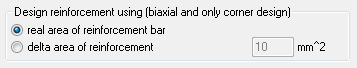
4.1.3.1.5.7.1 Area of reinforcement type
|
Group |
General > Calculation > Columns |
|
Type of parameter |
Radio button |
|
Mode: |
Advanced mode only |
|
Default: |
Real area of reinforcement bar |
|
Local setting |
NO |
|
Influence |
Only design reinforcement to column for biaxial and only corner design |
This setting allows to set type of area of reinforcement for biaxial and only corner design, which will be used for design of reinforcement. There are two possibilities:
|
Concrete setup (Design default) |
Member data |
|
|
|
The comparison of results for different reinforcement type and different delta are of reinforcement for columns with different size number of reinforcement is in table below.
|
Real area of reinforcement bars |
|
|
Delta area of reinforcement (0.2inch2) |
|
|
Delta area of reinforcement (0.02inch2) |
|
For method Only corner design the following principles are used
For real area of reinforcement bars – the diameter of bar increases according to list of basic diameter, which can be different for each code. The initial value of diameter for calculation is loaded from concrete setup, item Design default or from concrete member data.
For delta area of reinforcement – the diameter of bar is calculated from input value of delta area. The value delta area represents increasing area of one bar of reinforcement in each iteration step. The diameter of bars in each iteration step is calculated and it is rounded up to integer number.
4.1.3.1.5.7.2 Delta area of reinforcement
|
Group |
General > Calculation > Columns |
|
Type of parameter |
Edit box |
|
Mode: |
Advanced mode only |
|
Default: |
10 mm2 (Limit values from 0 to100000) 0.0155 inch2 (Limit values from 0.0155 to 1550) |
|
Local setting |
NO |
|
Influence |
Only design reinforcement to column for biaxial and only corner design |
This edit box is used for inputting area of reinforcement, which will be used for biaxial and only corner design. It is active only, if item Delta area of reinforcement is selected from combo box Area of reinforcement type.
In this group are described interaction formulas for biaxial bending calculation and user can set exponent for interaction formula
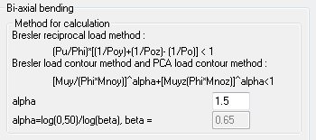
4.1.3.1.5.8.1 Alpha
|
Group |
General > Calculation > tab sheet Columns |
|
Type of parameter |
Edit box |
|
Mode: |
Advanced mode only |
|
Default: |
1.5 (Limit values from 1 to 5) |
|
Local setting |
NO |
|
Influence |
Only design reinforcement to column for biaxial bending calculation and Bressler load contour method |
Exponent of interaction formula for Bressler load contour method can be inputted via this paramet, see chapter see chapter "4.1 Concrete setup for 1D member". If exponent of interaction formula (value Alpha ) is 1,0, then Bressler load contour method can be used only for design reinforcement to column , where the following conditions is fulfilled
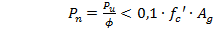
|
where |
|
|
Pu |
factored axial force |
|
f |
Strength reduction factor calculated by iterative calculation, loaded from concrete setup or from concrete member data, see chapter "4.1 Concrete setup for 1D member" |
|
fc’ |
specified compressive strength of concrete |
|
Ag |
gross area of concrete section |
If value Alpha =1 and conditions above is not fulfilled, then program finishes with errors 854 (Bresler load contour method cannot be used, because Pu > 0,1*fc*Ag*Phi. Use different value Alpha or different method)
4.1.3.1.5.8.2 Beta
|
Group |
General > Calculation > tab sheet Columns |
|
Type of parameter |
Edit box |
|
Mode: |
Advanced mode only |
|
Default: |
0.65 (Limit values from 0.5 to 1) |
|
Local setting |
NO |
|
Influence |
Only design reinforcement to column for biaxial bending calculation and PCA load contour method |
Exponent of interaction formula for PCA load contour method can be inputted via this parameter, see chapter "4.1 Concrete setup for 1D member"
The one of the most important parameter for biaxial bending calculation is ratio of reinforcement in y and z direction. There are three parameters which have influence to the ratio of the reinforcement
4.1.3.1.5.9.1 Ratio type
|
Group |
General > Calculation > tab sheet Columns |
|
Type of parameter |
Radio buttons |
|
Mode: |
Advanced mode only |
|
Default: |
Automatic |
|
Local setting |
Yes |
|
Influence |
Only design reinforcement to rectangular column for biaxial bending calculation |
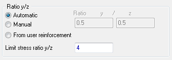
There are three possibilities for calculation ratio of reinforcement in biaxial bending calculation:
Ratio y/z = if σy = 0 MPa and σz = 0 MPa , then ratio_y/z = 1
|
where |
|
|
σ y |
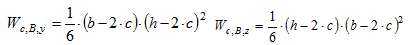
The bending stress around y-axis, σy = Muy/Wc,B,y |
|
σz |
The bending stress around y-axis, σz = Muz/Wc,B,z |
|
Muy(z) |
Factored (magnified) moment at section about the y (z) axis of LCS of the member |
|
Wc,B,y(z) |
Section modulus for biaxial calculation around y (z) axis calculated concrete cross-section without concrete cover
|
|
b,h |
dimension of rectangular cross-section |
|
c |
Concrete cover of the stirrup |

|
where |
|
|
x |
Input value in parameter Ratio y/z |
|
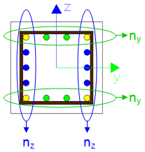
where ny is number of bars in y direction of LCS including corner bars nz is number of bars in z direction of LCS including corner bars
|
|
The user reinforcement can be defined for code ACI 318-05 only in local setting (via member data)
This option From user reinforcement will be taken into account only if some user reinforcement is defined in the column .If this condition is not fulfilled, the ratio y/z will be calculated automatically (Ratio type = Automatic).
4.1.3.1.5.9.2 Ratio y/z
|
Group |
General > Calculation > tab sheet Columns |
|
Type of parameter |
Edit box |
|
Mode: |
Advanced mode only |
|
Default: |
0,5 (Limit values from 0 to10) |
|
Local setting |
Yes |
|
Influence |
Only design reinforcement to rectangular column for biaxial bending calculation |
This edit box allows to input user value of ratio y/z. The ratio of reinforcement in y direction is inputted and the ratio in z direction is calculated by the program. This property is active, only if Ratio type = Manual
4.1.3.1.5.9.3 Limit stress ratio
|
Group |
General > Calculation > tab sheet Columns |
|
Type of parameter |
Edit box |
|
Mode: |
Advanced mode only |
|
Default: |
4 (Limit values from 0 to100) |
|
Local setting |
No |
|
Influence |
Only design reinforcement to rectangular column for biaxial bending calculation |
Design reinforcement with using biaxial bending calculation depends on value ratio y/z (ratio of reinforcement in y/z ), if check box Optimize the number of bars in c-s for biaxial calculation is OFF. If the ratio y/z is big, the program has to design many bars in one direction to interaction formula was fullfilled, but result of interaction formula is small. This solution is often uneconomical design of reinforcement, therefore user can set limit ratio y/z via property Limit stress ratio (ratio y/z )lim). If ratio y/z > (ratio y/z )lim or ratio y/z < 1/(ratio y/z )lim ,then program gives warning 245 (An unusual design situation encountered: the stress ratio y/z exceeds the preset limit of the required reinforcement is hardly acceptable.Please, check the concrete setup) and user should:
The possibilty of correction calculation, when warning 245 is appeared, is presented in the table-.
|
Setting |
Results |
|---|---|
|
Biaxial calculation, ratio type= Automatic, Optimalization=OFF, Real area of reinforcement bar |
|
|
Biaxial calculation, ratio type= Automatic, Optimalization=ON, Real area of reinforcement bar |
|
|
Uniaxial calculation(Sum), ratio type= Automatic, Optimalization=OFF, Real area of reinforcement bar |
|
|
Biaxial calculation, ratio type= Manual, ratio y/z = 0,5, Optimalization=OFF, Real area of reinforcement bar |
|
|
Biaxial calculation, ratio type= Automatic, Optimalization=OFF, Delta area of reinforcement bar, delta = 0.02inch2 |
|
There are the following items in group General > Calculation > Beams.
|
Group |
General > Calculation > Beams |
|
Type of parameter |
Checkbox |
|
Default: |
ON |
|
Local setting |
NO |
|
Influence |
Design of reinforcement |
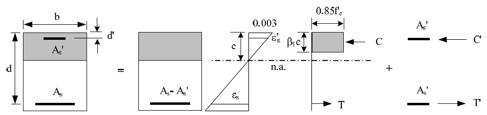
if this checkbox is set to YES, then compression reinforcement is automatically designed. This can happen when
Equilibrium was not found (583)
Depth of compression zone is bigger then allowed value – the tensile reinforcement is not fully exploited
|
Without compression reinforcement |
|
|
Without compression reinforcement |
|
|
Group |
General > Calculation > Beams |
|
Type of parameter |
Checkbox |
|
Default: |
ON |
|
Local setting |
NO |
|
Influence |
Design of reinforcement |
If this checkbox is set to YES the normal force from statical analysis is also taken into account for design of reinforcement
|
Group |
General > Calculation > Beams |
|
Type of parameter |
Checkbox |
|
Default: |
ON |
|
Local setting |
NO |
|
Influence |
Design of reinforcement |
If this checkbox is set to YES then member is checked if should be designed as column or not
IF 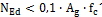 THEN member is considered as beam
IF 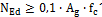 THEN member should be considered as column (E915) The user should change type of beam to column
|
Group |
General > Calculation > Beams |
|
Type of parameter |
Checkbox |
|
Default: |
OFF |
|
Local setting |
NO |
|
Influence |
Recalculated internal forces for design of reinforcement |
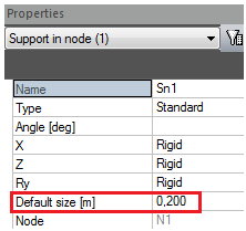
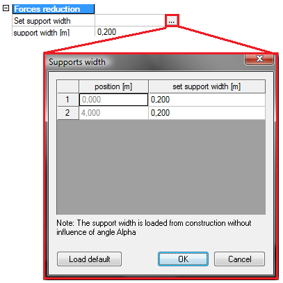
|
CMD |
Support width |
|
if concrete member data does not exist width of support will be loaded from the structure,
|
|
|
if concrete member data exists width of support will be loaded from Concrete member data > Force reduction
|
|
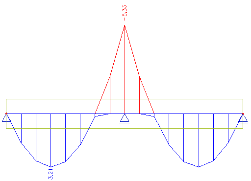
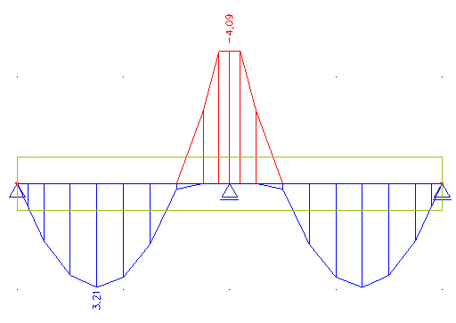
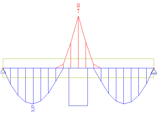
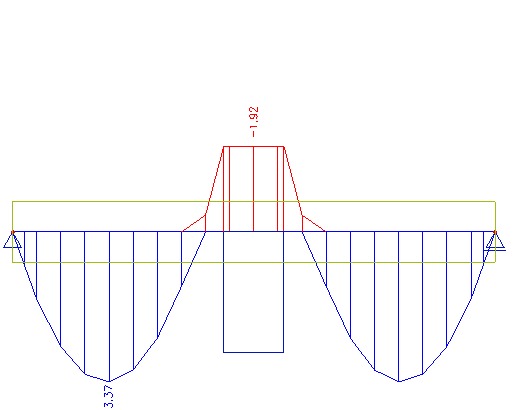
The comparison of the bending moments with and without capping for standard support and for column support is done in the following table
|
Moment capping |
NO |
YES |
|
Standard support |
|
|
|
Column support |
|
|
|
Group |
General > Calculation > Beams |
|
Type of parameter |
Checkbox |
|
Default: |
OFF |
|
Local setting |
NO |
|
Influence |
Recalculated internal forces for design of reinforcement |
If this checkbox is set ON then shear force is reduced according to type of reduction in recalculated forces (for more information see part related to “Reduce shear force”)
|
Group |
General > Calculation > Beams |
|
Type of parameter |
Radio button |
|
Default: |
OFF |
|
Local setting |
NO |
|
Influence |
Recalculated internal forces for design of reinforcement |
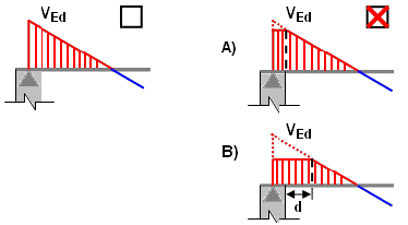
Type of calculation of reduced shear force
A) At the face (support/column) - shear force above the support is the same as shear force in the face of the support/column
B) At the effective depth from the face (support/column) – shear force is calculated at distance d (effective depth of cross-section) from the face of support/column
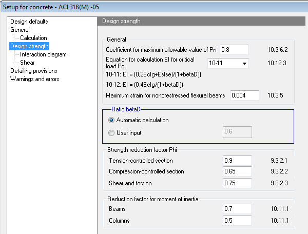
In this tab-sheet are parameters, which have influence directly to calculation design strength of the structure
|
Group |
Design strength |
|
Type of parameter |
Edit box |
|
Default: |
0.8 (Limit values from 0.5 to1) |
|
Local setting |
No |
|
Influence |
Only design reinforcement to column |
Design axial strength φ·Pn of compression members shall not be taken greater than φ·Pn,max, computed according to ACI 318-05,clause 10.3.6.1.The percentage of maximum allowable stresses from nominal axial strength can be set by this parameter, it means that following formula is used for calculation

|
where |
|
|
x |
Coefficient for calculation maximum allowable value Pn |
|
f |
Strength reduction factor calculated by iterative calculation, loaded from concrete setup or from concrete member data, see chapter "4.1 Concrete setup for 1D member" |
|
coeffc |
coefficient for reduction specified compressive strength loaded from concrete setup |
|
fc’ |
specified compressive strength of concrete |
|
Ag |
gross area of concrete section |
|
Ast |
total area of non-prestressed longitudinal reinforcement |
|
fy |
specified yield strength of reinforcement |
The area of reinforcement is not subtracted from area of concrete in design reinforcement, because area of reinforcement is unknown, where this check is done
|
Group |
Design strength |
|
Type of parameter |
Combo box |
|
Default: |
Equation 10-11 |
|
Local setting |
No |
|
Influence |
Equation for calculation stiffness for the critical column load |
In calculation magnified moments for sway or non-sway frame (see chapter "7.2 Internal forces for 1D members (beam, beam as slab, column)"), it is necessary to calculate critical column load (value Pc). This critical column load (Euler buckling load) depends on flexural stiffness of compression member (value EI), which in code ACI 318-05 can be calculated by two ways.
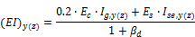
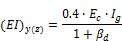
|
where |
|
|
Ec |
modulus of elasticity of concrete, see chapter "3.1 Concrete" |
|
Ig,y(z) |
moment of inertia of gross concrete section about y(z) centroidal axis of LCS neglecting reinforcement |
|
Ec |
modulus of elasticity of reinforcement, see chapter "3.2 Reinforcement" |
|
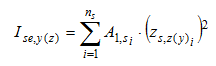
Ise,y(z) |
moment of inertia of reinforcement about y(z) centroidal axis of LCS axis of member cross section, see chapter "4.1 Concrete setup for 1D member" |
|
βd |
ratio used to compute magnified moments in columns due to sustained loads, see chapter "4.1 Concrete setup for 1D member" |
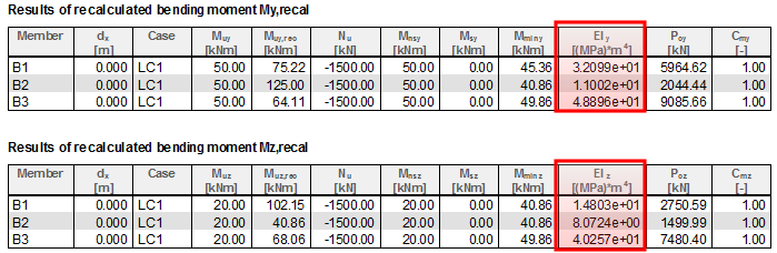
The calculated values of flexural stiffness’s are presented in the service Internal forces (tree Concrete > 1D member), if values My,recalc or My,recalc are selected, see chapter "7.2 Internal forces for 1D members (beam, beam as slab, column)"
|
Group |
Design strength > Strength reduction factor Phi |
|
Type of parameter |
Edit box |
|
Default: |
0.004 |
|
Local setting |
NO |
|
Influence |
Design of longitudinal reinforcement for beams and beam as slab |
For nonprestressed flexural members and nonprestressed members with factored axial compressive load less than 0.10fc′Ag the strain in most tensioned reinforcement (value εt) has to be greater than defined value in edit box, see chapter "8.2 Design of reinforcement for 1D members (beams, beams as slab, columns)" and "8.2 Design of reinforcement for 1D members (beams, beams as slab, columns)".
εt ≥εt,max =0,004
If condition above is not fulfilled, then the calculation finished with error 916 (The cross-section is not ductile).
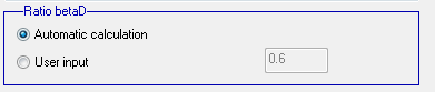
Creep due to sustained load will increase the lateral deflections of a column and hence the moment magnification..This is approximated for design by reducing the stiffness EI (see chapter 4.1.4.2 Equation for calculation EI for calculation Pc) used for calculation critical column load (value Pc) by dividing EI by equation (1+βd). There are two basic properties (two type of calculation factor +βd ) in this group:
|
Group |
Design strength |
|
Type of parameter |
Radio button |
|
Default: |
Automatic calculation |
|
Local setting |
Yes |
|
Influence |
Calculation of magnified moment for compression member |
This setting allows to set type of calculation of factor βd:

For automatic calculation, factor βd is calculated in each sections of the compression column, it means that in each section at length of compression member the different value can be taking into account
For user input the same value in each section of compression member is used
|
Group |
Design strength |
|
Type of parameter |
Edit box |
|
Default: |
0.6 (Limit values from 0 to10) |
|
Local setting |
Yes |
|
Influence |
Calculation of magnified moment for compression member |
This edit box is used for inputting user input of factor βd . It is active only, if item User input is selected in group Ratio BetaD
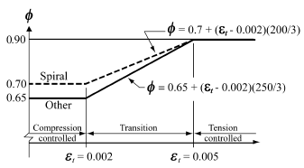
Design strength of the structure is calculated multiplying the nominal strength by a strength reduction factor φ. The values of this factor for different situation are defined in ACI-318-05, clause 9.3.2. Here user can define default value of strength reduction factor for basic situation.
|
Group |
Design strength > Strength reduction factor Phi |
|
Type of parameter |
Edit box |
|
Default: |
0.65 |
|
Local setting |
Yes |
|
Influence |
Calculation strength reduction factor for design of longitudinal reinforcement |
This factor should be used for calculation if tensile reinforcement in reinforcement (value εt) is lesser than 0.002.
For design reinforcement of beams (see chapter "8.2 Design of reinforcement for 1D members (beams, beams as slab, columns)") this factor is used in following case:
For design reinforcement in column (see chapter "8.2 Design of reinforcement for 1D members (beams, beams as slab, columns)") this factor is used in following cases,
|
Group |
Design strength > Strength reduction factor Phi |
|
Type of parameter |
Edit box |
|
Default: |
0.75 |
|
Local setting |
Yes |
|
Influence |
Calculation strength reduction factor for design of shear reinforcement |
This factor is used for calculation design shear strength, see chapter "8.2 Design of reinforcement for 1D members (beams, beams as slab, columns)".
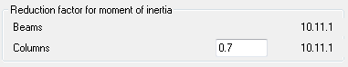
According to clause 10.1.1 in ACI 318-05, it is possible to use alternative values of moment of inertia for the calculation. Reduction factor for moment of inertia of columns and beams can be set in this group and this reduction factors will be only used for calculation value ψAy(z) and ψBy(z), which are used for calculation effective length factor according code ACI (code dependent method for calculation effective length factor ), see chapter "5.4 Member buckling data".
|
Group |
Design strength > Reduction factor for moment of inertia |
|
Type of parameter |
Edit box |
|
Default: |
0.35 (Limit values from 0 to1) |
|
Local setting |
NO |
|
Influence |
Calculation effective length factor according code ACI |
This factor is used for reduction moment of inertia of beams in calculation coefficient ψAy(z) and ψBy(z), which are used for calculation effective length factor according to code dependent method
Ig,red,y(z) = redb· Ig,y(z)
|
where |
|
|
Ig,y(z) |
moment of inertia of gross concrete section about y(z) centroidal axis of LCS neglecting reinforcement |
|
redb |
Reduction factor for beams set in edit box |
|
Group |
Design strength > Reduction factor for moment of inertia |
|
Type of parameter |
Edit box |
|
Default: |
0.7 (Limit values from 0 to1) |
|
Local setting |
NO |
|
Influence |
Calculation effective length factor according code ACI |
This factor is used for reduction moment of inertia of columns in calculation coefficient ψAy(z) and ψBy(z), which are used for calculation effective length factor according to code dependent method
Ig,red,,y(z) = redc· Ig,y(z)
|
where |
|
|
Ig,y(z) |
moment of inertia of gross concrete section about y(z) centroidal axis of LCS neglecting reinforcement |
|
redc |
reduction factor for columns set in edit box |
There is only one value in part Design strength > Shear.
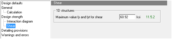
|
Group |
General > Calculation > Beams |
|
Type of parameter |
Radio button |
|
Default: |
OFF |
|
Local setting |
NO |
|
Influence |
Recalculated internal forces for design of reinforcement |
This value is maximal available yield strength of the reinforcement used for the design of shear reinforcement. If user inputs bigger value then maximal value from concrete setup is taken into account
Generally detailing provisions are split to detailing provisions for beams and columns. Each type of memebr (beam or column) has the different detailing provisions for design of longitudinal and shear reinforcement.
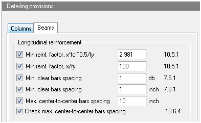
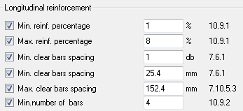
There are the following items in the part Detailing provisions > Beams > Longitudinal reinforcement.
|
Group |
Detailing provisions > Beams |
|
Type of parameter |
Check box + edit box |
|
Default: |
ON |
|
Local setting |
NO |
|
Influence |
Design of longitudinal reinforcement |
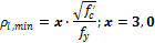
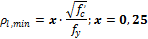
This value is minimal reinforcement factor during design of longitudinal reinforcement in beams. Value x is user defined value and default is 3,0 for US unit format and 0,25 for metric format
|
Unit format |
Formula |
|
US |
|
|
Metric |
|
|
Group |
Detailing provisions > Beams |
|
Type of parameter |
Check box + edit box |
|
Default: |
ON |
|
Local setting |
NO |
|
Influence |
Design of longitudinal reinforcement |
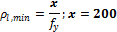
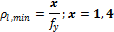
This value is minimal reinforcement factor during design of longitudinal reinforcement in beams. Value x is user defined value and default is 200 for US unit format and 1,4 for metric format
|
Unit format |
Formula |
|
US |
|
|
Metric |
|
|
Group |
Detailing provisions > Beams |
|
Type of parameter |
Check box + edit box |
|
Default: |
ON |
|
Local setting |
NO |
|
Influence |
Design of longitudinal reinforcement |
This value is minimal strain in reinforcement which is allowed for beams where axial load is ; otherwise the cross-section is not ductile
|
Group |
Detailing provisions > Beams |
|
Type of parameter |
Check box + edit box |
|
Default: |
ON |
|
Local setting |
NO |
|
Influence |
Design of longitudinal reinforcement |
This value prescribes minimum clear distance between bars; default value is diameter of the bar
|
Group |
Detailing provisions > Beams |
|
Type of parameter |
Check box + edit box |
|
Default: |
ON |
|
Local setting |
NO |
|
Influence |
Design of longitudinal reinforcement |
This value prescribes minimum clear distance between bars; default value is 1 inch
|
Group |
Detailing provisions > Beams |
|
Type of parameter |
Check box + edit box |
|
Default: |
OFF |
|
Local setting |
NO |
|
Influence |
Design of longitudinal reinforcement |
This is the user defined value of maximal clear spacing between longitudinal bars. It is code independent value
|
Group |
Detailing provisions > Beams |
|
Type of parameter |
Check box + edit box |
|
Default: |
ON |
|
Local setting |
NO |
|
Influence |
Design of longitudinal reinforcement |
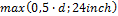
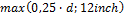
This item prescribes maximal allowed centre to centre bars spacing between longitudinal bars based on the chapter 10.6.4 from ACI 318-05.
There are the following items in the part Detailing provisions > Beams > Shear reinforcement.
|
Group |
Detailing provisions > Beams |
|
Type of parameter |
Check box + combobox + edit box |
|
Default: |
ON |
|
Local setting |
NO |
|
Influence |
Design of shear reinforcement |
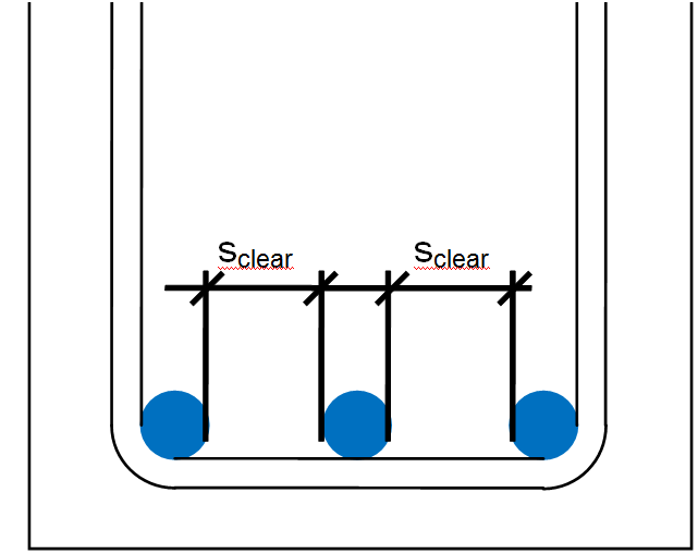
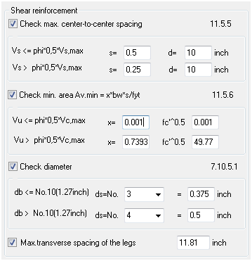
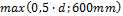
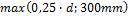
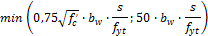
This item prescribes maximal allowed centre to centre spacing between stirrups legs based on the chapter 11.5.5 from ACI 318-05.
There are two values in combobox
| Unit format |
Formula |
spacing |
| US |
|
|
|
|
|
| Metric |
|
|
|
|
|
Where value

|
Group |
Detailing provisions > Beams |
|
Type of parameter |
Check box + combobox + edit box |
|
Default: |
ON |
|
Local setting |
NO |
|
Influence |
Design of shear reinforcement |
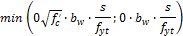
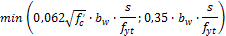
This item prescribes minimal area of shear reinforcement based on the chapter 11.5.6 from ACI 318-05.
There are two values in combobox
| Unit format | Formula | spacing |
| US |
|
|
|
|
|
|
| Metric |
|
|
|
|
|
|
Group |
Detailing provisions > Beams |
|
Type of parameter |
Check box + combobox + edit box |
|
Default: |
ON |
|
Local setting |
NO |
|
Influence |
Design of shear reinforcement |
This item prescribes minimal diameter of shear reinforcement based on the chapter 7.10.5.1 from ACI 318-05.
There are two values in combobox
| Unit format | Formula | spacing |
| US |
|
|
|
|
|
|
| Metric |
|
|
|
|
|
|
Group |
Detailing provisions > Beams |
|
Type of parameter |
Check box + combobox + edit box |
|
Default: |
ON |
|
Local setting |
NO |
|
Influence |
Design of shear reinforcement |
This item prescribes maximal allowable transverse spacing of the stirrups legs. It is code independent value
There are defined detailing provisions for design of longitudinal reinforcement to column
|
Group |
Detailing provisions > tab-sheet Columns |
|
Type of parameter |
Check box +edit box |
|
Default: |
Check box is ON, value in edit box = 1% |
|
Local setting |
No |
|
Influence |
Design longitudinal reinforcement to column |
If this check box is ON, then minimum area of longitudinal reinforcement is checked according to clause 10.9.1 in ACI 318-05. If area of longitudinal reinforcement is lesser than minimum area of reinforcement, then
As = As,min = x·Ag /100
and design of longitudinal reinforcement finishes with warning 2 (The main reinforcement area was designed according to min. Required reinforcement percentage)
|
where |
||
|
Ag |
gross area of concrete section |
|
|
x |
Value of minimum percentage loaded from edit box |
|
|
Group |
Detailing provisions > tab-sheet Columns |
|
Type of parameter |
Check box +edit box |
|
Default: |
Check box is ON, value in edit box = 8% |
|
Local setting |
No |
|
Influence |
Design longitudinal reinforcement to column |
If this check box is ON, then maximum area of longitudinal reinforcement is checked according to clause 10.9.1 in ACI 318-05. If area of longitudinal reinforcement is greater than maximum area of reinforcement ( As> As,max = x·Ag /100 ) then design of longitudinal reinforcement finishes with warning 502 (The percentage of designed reinforcement is higher than the maximum percentage)
|
where |
||
|
Ag |
gross area of concrete section |
|
|
x |
value of maximum percentage loaded from edit box |
|
|
Group |
Detailing provisions > tab-sheet Columns |
|
Type of parameter |
Check box + edit box |
|
Default: |
Check box is ON, value in edit box = 1 |
|
Local setting |
NO |
|
Influence |
Design longitudinal reinforcement to column |
If this check box is ON, then minimum clear spacing between bars is checked according to clause 7.6.1 in ACI 318-05. If clear spacing of bars is lesser than minimum spacing then design of longitudinal reinforcement finishes with the following warnings
|
Warning |
Description |
Cause |
|
134 |
Tha bar distance for the Y-direction is too small |
The minimum spacing of bars in direction of y-axis of LCS of the member for rectangular cross-section does not satisfy |
|
136 |
Tha bar distance for the Z-direction is too small |
The minimum spacing of bars in direction of z-axis of LCS of the member for rectangular cross-section does not satisfy |
|
138 |
The bars distance is too small |
The minimum spacing of bars in circular cross-section is does not satisfy |
|
Group |
Detailing provisions > tab-sheet Columns |
|
Type of parameter |
Check box + edit box |
|
Default: |
Check box is ON, value in edit box = 25,4 mm (1 inch) |
|
Local setting |
NO |
|
Influence |
Design longitudinal reinforcement to column |
If this check box is ON, then minimum clear spacing between bars is checked according to clause 7.6.1 in ACI 318-05. If clear spacing of bars is lesser than minimum spacing then design of longitudinal reinforcement finishes with If clear spacing of bars is lesser than minimum spacing then design of longitudinal reinforcement finishes with the following warnings.
|
Warning |
Description |
Cause |
|
134 |
Tha bar distance for the Y-direction is too small |
The minimum spacing of bars in direction of y-axis of LCS of the member for rectangular cross-section does not satisfy |
|
136 |
Tha bar distance for the Z-direction is too small |
The minimum spacing of bars in direction of z-axis of LCS of the member for rectangular cross-section does not satisfy |
|
138 |
The bars distance is too small |
The minimum spacing of bars in circular cross-section does not satisfy |
|
Group |
Detailing provisions > tab-sheet Columns |
|
Type of parameter |
Check box + edit box |
|
Default: |
Check box is ON, value in edit box = 6inch (152.4mm) |
|
Local setting |
NO |
|
Influence |
Design longitudinal reinforcement to column |
If this check box is ON, then centre-centre spacing between bars is checked. This is code independently check. If this centre-centre spacing of bars is bigger than maximum spacing then design of longitudinal reinforcement finishes with the following warnings
|
Warning |
Description |
Cause |
|
133 |
Tha bar distance for the Y-direction is too big |
The centre-centre maximum spacing of bars in direction of y-axis of LCS of the member for rectangular cross-section does not satisfy |
|
135 |
Tha bar distance for the Z-direction is too big |
The centre-centre maximum spacing of bars in direction of z-axis of LCS of the member for rectangular cross-section does not satisfy |
|
137 |
The bars distance is big |
The centre-centre maximum spacing of bars in circular cross-section does not satisfy |
|
Group |
Detailing provisions > tab-sheet Columns |
|
Type of parameter |
Check box +edit box |
|
Default: |
Check box is ON, value in edit box = 4 |
|
Local setting |
No |
|
Influence |
Design longitudinal reinforcement to column |
If this check box is ON, then in design of reinforcement minimum number of bars according to clause 10.9.2 in ACI 318-05 is used for calculation, though number of bars from design reinforcement is lesser. For rectangular column minimum numbers of bars is always 4, independently on value defined in this property. This setting is used for number of bars in circular column.
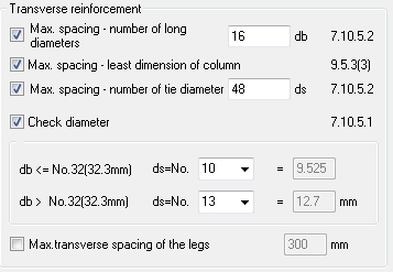
There are defined detailing provisions for design of transverse reinforcement (ties) to column
|
Group |
Detailing provisions > tab-sheet Columns |
|
Type of parameter |
Check box + edit box |
|
Default: |
Check box is ON, value in edit box = 16 |
|
Local setting |
NO |
|
Influence |
Design of transverse reinforcement to column |
If this check box is ON, then spacing of bars as multiple of diameter of longitudinal reinforcement bars according to clause 7.10.5.2 in ACI 318-05 is taken into account for design transverse reinforcement (maximum vertical spacing of ties)
ss,min,1 = x·db
|
where |
|
|
db |
diameter of longitudinal reinforcement loaded
|
|
x |
value of maximum spacing loaded from edit box |
|
Group |
Detailing provisions > tab-sheet Columns |
|
Type of parameter |
Check box |
|
Default: |
Check box is ON |
|
Local setting |
NO |
|
Influence |
Design of transverse reinforcement to column |
If this check box is ON, then spacing of bars as least dimension of column according to clause 7.10.5.2 in ACI 318-05 is taken into account for design transverse reinforcement (maximum vertical spacing of ties)
ss,min,2 = min (b;h)
|
where |
|
|
b,h |
the dimensions of cross-section of compression member in direction of y(z) axis of LCS. For different shape of cross-section than rectangular shape, the dimensions of circumscribed rectangular is taken into account |
|
Group |
Detailing provisions > tab-sheet Columns |
|
Type of parameter |
Check box + edit box |
|
Default: |
Check box is ON, value in edit box = 48 |
|
Local setting |
NO |
|
Influence |
Design of transverse reinforcement to column |
If this check box is ON, then spacing of bars as multiple of tie diameter according to clause 7.10.5.2 in ACI 318-05 is taken into account for design transverse reinforcement (maximum vertical spacing of ties)
ss,min,3 = x·ds
|
where |
|
|
ds |
diameter of shear reinforcement (tie diameter)
|
|
x |
value of maximum spacing loaded from edit box |
|
Group |
Detailing provisions > tab-sheet Columns |
|
Type of parameter |
Check box + two edit boxes |
|
Default: |
Check box is ON, value in edit box = 3 (10) value in edit box = 4 (13) |
|
Local setting |
NO |
|
Influence |
Design of transverse reinforcement to column |
If this check box is ON, then minimum diameter of shear reinforcement (ties) according to clause 7.10.5.1 in ACI 318-05 is checked during design of shear reinforcement. Minimum diameter of shear reinforcement depends on diameter of longitudinal reinforcement, which enclosed, see table below.
| Unit format | Diameter of longitudinal reinforcement | Minimum shear diameter |
| US |
|
|
|
|
|
|
| Metric |
|
|
|
|
|
If diameter of shear reinforcement is lesser than minimum diameter of shear reinforcement, then design of shear reinforcement finishes with warning 163 (The profile diameter of shear reinforcement is lesser than permitted). In this case, value shear reinforcement has to be increased in concrete setup or concrete member data.
If diameter of shear reinforcement is lesser than minimum diameter of shear reinforcement, then design of shear reinforcement finishes with warning 163 (The profile diameter of shear reinforcement is lesser than permitted). In this case, value shear reinforcement has to be increased in concrete setup or concrete member data.
|
Group |
Detailing provisions > tab-sheet Columns |
|
Type of parameter |
Check box + edit box |
|
Default: |
Check box is OFF, edit box = 11,81 inch (300 mm) |
|
Local setting |
NO |
|
Influence |
Design of transverse reinforcement to column |
The value from edit box (value st,max) is used for calculation number of cuts of shear reinforcement independently if check box is ON or OFF. This value is used for:
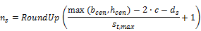
Number of cuts is calculated according to formula
|
where |
|
|
ds |
diameter of shear reinforcement (tie diameter)
|
|
bcen |
width of cross-section in centroid of concrete cross-section |
|
hcen |
height of cross-section in centroid of concrete cross-section |
|
c |
The nominal value of concrete cover, value presented in property Concrete cover |
|
st,max |
the maximum transverse spacing of the legs loaded from value defined in edit box |