![]()
|
||
|
|
||
SCIA Engineer offers the user to execute a stability analysis which obtains the buckling shape of the structure for a given stability combination. That buckling shape occurs when a certain critical normal force Ncr,i (Euler's critical load) is achieved in the member(s).
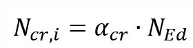
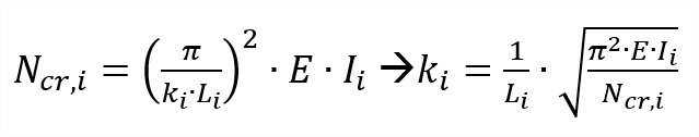
Euler's critical load (Ncr,i) is known after a stability analysis therefore via Euler's formula we can obtain the buckling factor because:
| Ncr,i | Euler's critical load |
| αcr | Critical load factor for the selected stability combination |
| NEd | Design loading in the member |
| E | Modulus of Young |
| ki | Buckling factor for axis i (y-y or z-z) |
| Ii | Moment of inertia of axis i (y-y or z-z) |
| Li | System length of axis i (y-y or z-z) |
In case of a non-prismatic member, the moment of inertia is taken in the middle of the element.
Obtaining the buckling factor from stability is the most accurate approach that is available within SCIA Engineer. You can do it as follows:
1) Activate the functionality stability in the project data dialog
2) Create stability combinations
3) Refine the finite element mesh of 1D-members to at least 5 in the mesh settings
4) Define in the solver setup how many eigenvalues (i.e. how many buckling shapes per stability combination) need to be obtained
5) Run the stability combination
6) Determine which stability combination causes buckling in the member by evaluating the 3D-deformations per stability combination.
Two stability combinations need to be obtained for major axis buckling (ky) and minor axis buckling (kz).
Below an example of a stability combination which causes minor axis buckling (kz). This stability combination can be used for obtaining kz.
 buckling")
Below an example of a stability combination which causes major axis buckling (ky). This stability combination can be used for obtaining ky.

7) Create and assign stability member data via the material service (e.g. steel) -> Beams -> Member check data -> Stability member data.
It is important to emphasize that the correct stability combinations are selected for ky and kz (i.e. these should induce major axis and minor axis buckling on this member).

Once defined click on OK and select the target member(s). A label SMD# will appear on these members.
Now you are done. Meaning that the buckling factors on the members with stability member data will be obtained from the stability analysis.
Below you can see a manual verification of the obtained buckling factors from stability.
