![]()
|
||
|
|
||
Calculation of resistance of a bolt-row containing 4 bolts is based on the publication: Application of Eurocode 3 to Steel connections with four bolts per horizontal (J.-F. Demonceau, K. Weynand, J.-P. Jaspart and C. Müller) - 2010.
The reference makes a clear distinction between so-called "Outer bolt-row" and "Inner bolt-row" in order to define T-stubs, either vertical or horizontal. Within SCIA Engineer this is related to the classification of bolt-row.
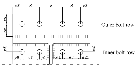
For the Outer bolt-row, the T-stub is vertical, and takes into account two bolts (the T-stub web is the beam flange). The presence of four bolts within this row only influence the values of the effective lengths. The modification of effective length formulas touches only one bolt-row classification:
For the Inner bolt-row, the T-stub is horizontal, and takes into account four bolts (the T-stub web is the beam web). The presence of four bolts within this row is taken into account by modification of the effective lengths and by used formulas for bolt-row resistance. The modification of effective length formulas touches these bolt-row classifications:
For further info on the classification of bolt-row see the chapter "Classification of Bolt-rows".
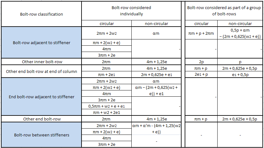
Effective length formulas for column flange classifications used for 4 bolt per row:
Effective length formulas for end-plate classifications used for 4 bolt per row:
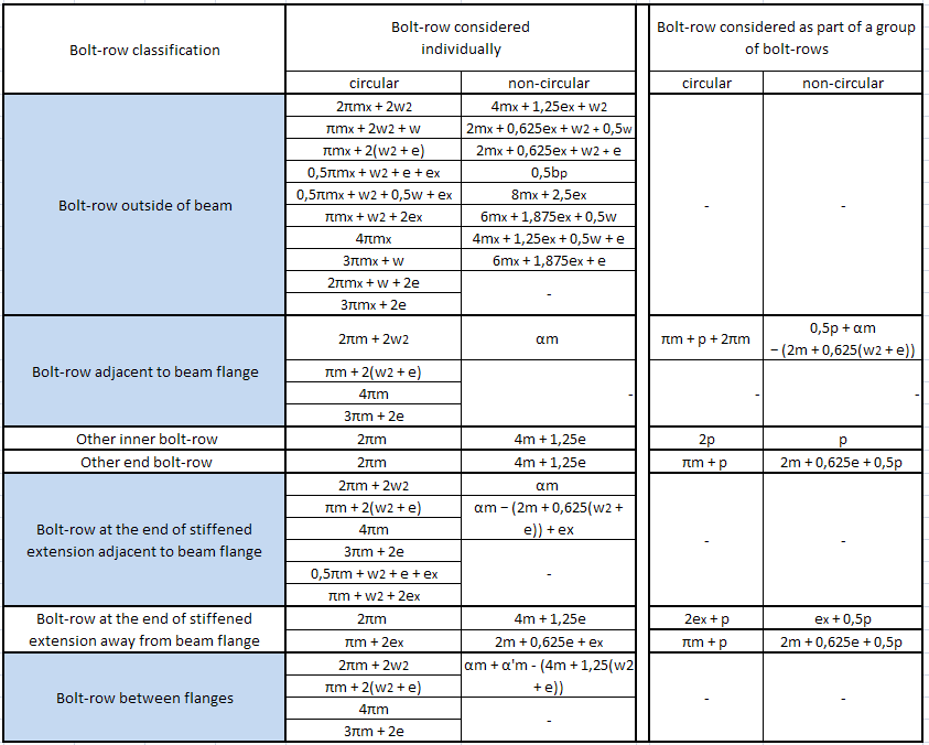
The classifications with white background were not modified in comparison with standard 2 bolts per row formulas. These bolt-rows are neglecting the 2 additional side bolts in the calculation of the tension resistance of the bolt-row, and therefore are used in full for shear resistance even if the bolt-row is in tension.
Extract of EN 1993-1-8 Article 6.2.4.1, Table 6.2 Mode 2 formulas to predict the design resistance of T-stubs for each possible failure mode in case Prying forces will develop.
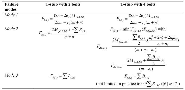
The parameters used by the formulas are in general defined by EN 1993-1-8 Article 6.2.4.1, Table 6.2 with the exception that for a T-stub with 4 bolts (bolt row with the blue background in the tables above), n =(w2+e) with n ≤ 1,25*m, n1 = w2 and n2 = e with n2 ≤ 1,25*m+n1.
Conversion of the parameters used in the reference and SCIA Engineer:
|
Bolt-row picture |
FT,Rd formulas |
SCIA Engineer |
|
m1 |
m |
m |
|
e1 |
n1 |
w2 |
|
e2 |
n2 |
e |
Summary:
If no prying forces will develop, initial formulas are to be used for Mode 1 and 2 resistances. Mode 3 resistance is modified with the coefficient of 0.9.
An additional modification on the level of calculation of FT,Rd of groups of bolt-rows is implemented in the SCIA Engineer. The reason for this is, that reference does not specify which FT,Rd formulas should be used for groups of bolt-rows which contain bolt-rows with modified effective lengths (calculated as 4 bolts in a row) and those not modified (calculated as 2 bolts in a row) in case prying forces will develop. If a group of bolt-rows containing both types of bolt-rows is found and for this group prying forces would develop, this group is removed from the calculation. The removal is done only for components "Column flange in bending" and "End-plate in bending". In calculation of another connection components the groups are used normally.
The "Outer bolt-row", as described above, is excluded from this modification, since it cannot be part of a group anyway. Only "Inner bolt-rows", as given by the reference, are possibly removed.
The calculation of shear force resistance VRd, and possible different usage of the inner and outer bolts in a bolt-row is accounted for. The reduction given by EN 1993-1-8 Art 6.2.2 of the shear resistance of the bolt-row is implemented according to the diagram below:
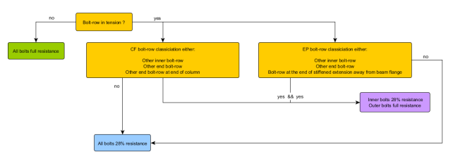
Inner and outer bolts in this context means the bolts which are closer or more far to the column/beam web.
For further info on the calculation of shear force resistance see the chapter "Shear force resistance".