![]()
|
||
|
|
||
Component is calculated according to EN 1993-1-8 Art 6.2.6.1.
(1) Not implemented.
(2) The calculation within SCIA Engineer is valid also for a double-sided joint in which the beam depths are not similar or for stiffened column web panel.
(4) To take the additional resistance into account, the "Use stiffeners in column web panel resistance" has to be activated in the connection setup and both top and bottom stiffeners are present in the connection.
For calculation of plastic moment resistance of a column flange a separate calculation for each flange is used:


For calculation of plastic moment resistance of a stiffener a width of the column is considered.

It is assumed that both stiffeners are the same and fulfil the minimum criteria based on the connected beam. Values of tf,stif and fy,stiff are taken equal to the beam tf and fy.
Resistance Vwp,Rd is calculated as:

which has to be smaller than:

(5) When a diagonal stiffener is activated in a connection, the resistance of the component is taken equal to the "Beam flange and web in compression" component ((See also chapter: "Beam flange and web in compression"). Triangular diagonal stiffener is not recognized as a stiffener, only rectangular diagonal stiffener is taken into account.
(6) The increase of the Avc area due to the presence of web doubler is implemented according to the article as bs*tw also for case 2 web plates.
(8)-(13) Checks not implemented.
Component is calculated according to EN 1993-1-8 Art 6.2.6.2.
(1)The beff,c,wc for bolted connections is calculated according to the formula (6.11), where:

with:
| sp_top | spread increase due to the dispersion through the end plate at top of the compression flange |
| sp_bot | spread increase due to the dispersion through the end plate at bottom of the compression flange |
For bolted end-plate connections, normally both sp_top and sp_bot distances are equal to ep due to the dispersion at 45°, but if:

Effective width beff,c,wc for a bolted perpendicular connection:

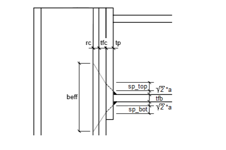
with:
| ep | thickness of end-plate |
| a | size of the flange weld |
| tfb | thickness of a beam flange |
| tfc | thickness of a column flange |
| Platebot_ext | bottom extension of the end-plate |
The same logic will be used in case plate haunch is defined , since the center of the compression is located within bottom beam flange (See also chapter: "Center of compression").

Effective width beff,c,wc for a bolted haunch connection:

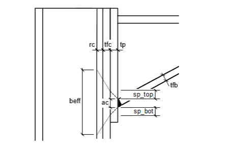
with:
| ep | thickness of end-plate |
| tfb | thickness of beam flange |
| tfc | thickness of a column flange |
| ac | size of the weld between haunch and end-plate / column |
| α | angle between column and the flange (haunch input degree) |
| Platebot_ext | bottom extension of the end-plate |
(2)To take the effect of axial force and bending moment in the column on the design resistance of the column web in compression into account, user has to activate "Include stress reduction in column web" check box in the connection setup. Only then the reduction coefficient kwc is printed on the output. Internal forces for the determination of the compressive stress σcom,Ed are taken from the node of the connection. The section for the internal forces is however not from the node directly but from the section right next to it, in the direction to the center of compression.
(5)When a stiffener at the location of the center of compression is activated on a column side of a connection, the resistance of the component is taken equal to the "Beam flange and web in compression" component (See also chapter: "Beam flange and web in compression").
(6)Column web thickness twc is taken alone, or as 1,5*twc or 2*twc, based on the presence of one or two web doublers. Shear area Avc for determination of ω values is taken from "Column web in shear component" (See also chapter: "Column web panel in shear").
Component is calculated according to EN 1993-1-8 Art 6.2.6.3.
(3)The effective width beff,t,wc used in the formula (6.15) for the calculation of the design tension resistance of column web Ft,wc,Rd for a bolted connection, are taken equal to the effective length of the "Column flange in transverse bending" component, with respect to the failure mode (See also chapter: "Column flange in transverse bending".
(6)If a transverse web stiffener is found in the tension zone of a column, it is assumed, that the component will not fail and the resistance of each bolt-row is taken equal to the "Beam flange and web in compression" component.
(8)For the calculation of tw,eff in case of a presence of web doubler it is assumed, that longitudinal welds are fillet welds with a throat thickness satisfying the given condition, therefore the coefficient of 1,4 respectively 1,3, based on the used material, is used.
Component is calculated according to EN 1993-1-8 Art 6.2.6.4.
There is a distinction in the EN 1993-1-8 between un-stiffened (6.2.6.4.1) and stiffened (6.2.6.4.2) column flange, but since the content of article 6.2.6.4.1 can be also found in article 6.2.6.4.2, the remarks below are related to that article.
(1)+(3)See chapter: "Group of bolt-rows".
(2)The alternative method given in Art 6.2.4.1 by Table 6.2 may be used by activating "Use alternative method for Ft,1,Rd" check box in the connection setup. (See also chapter: "Bolt elongation length")
(5)The effective lengths leff of an equivalent T-stub flange is using the values for each bolt-row given in Table 6.5 with one exception. This exception concerns calculation of non-circular pattern for bolt-rows classified as " End bolt-row adjacent to a stiffener ". In addition to the formula "e1+α*m-(2*m + 0,625*e)" an additional criterion of "α*m" is used. The minimum of these values is then used as leff,nc. (See also chapters: "Classification of Bolt-rows", "Alpha coefficient")
Note: Vertical distance e1
The EN 1993-1-8, Art 3.5 Figure 3.1 specifies e1 as the end distance from the center of a bore hole to the adjacent end of column flange, measured in the direction of load transfer.
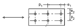
Within SCIA Engineer this e1 distance is measured from the center of an edge bolt to the appropriate end of a column, where the connection is defined. All internal nodes with possible beams and connections are neglected.
(6)Not implemented.
Component is calculated according to EN 1993-1-8 Art 6.2.6.5.
(1)The alternative method given in Art 6.2.4.1 by Table 6.2 may be used by activating "Use alternative method for Ft,1,Rd" check box in the connection setup. (See also chapter: "Bolt elongation length")
(2)See chapter: "Group of bolt-rows".
(4)Table 6.6 does not provide any formulas for such bolt-rows classified as "Bolt-row outside of beam" for calculation of effective lengths leff for bolt-row considered as part of a group of bolt-rows. Within SCIA Engineer this means, that for a connection design, on tension side of an end-plate it is not allowed to have more than one bolt-row classified as "Outside of a beam". If more bolt-rows, classified as Outside of Beam, are found on the tension side of the conencted beam, the Error message is displayed and connection design proceedure is terminated. (See also chapters: "Classification of Bolt-rows", "Alpha coefficient")
If an end-plate extension is found beyond the height of the existing plate haunch and a bolt-row is defined within, or even outside, this haunch, software recognizes this geometry as not consistent with the yield line patterns and warning is being printed in the output. In this case a possible "jump" of yield line patterns may occur, which is not covered by EN. A plate haunch gap near beam flange is assumed not to influence the yield line patterns.
Component is calculated according to EN 1993-1-8 Art 6.2.6.7.
(1)The component resistance Fc,fb,Rd is calculated with equation (6.21), using the design moment resistance of the beam cross-section Mc,Rd calculated with influence of haunch/es if aplicable, If a connected member is inclined the Mc,Rd calculation does not take this inclination into account. The haunches without flanges are also ignored in the Mc,Rd caluclation.
The influence of the inclined section and inclined haunch flange is neglected in calculation of the leverage arm hb-tfb. Different thicknesses of beam and haunch flange are however taken into account.
When calculation the section with one REAL haunch with flange, the leverage arm hb-tfb.is given as:

with:
| (hb-tfb) | leverage arm |
| hb | height of the beam without haunch |
| tfb | thickness of the beam flange |
| hfull | height of the haunch at the full end |
| lfull | length of the haunch from the start to the full end |
| tfh | thickness of the haunch flange |
| lface | length of the haunch from the start to the connection face |
When calculation the section with plate haunch, the leverage arm hb-tfb.is calculated as if the haunch is not defined.
The inclination of the beam/haunch flange is not taken into account in calculation of leverage arm hb-tfb neither in Mc,Rd.
The rule, described by the last sentence of this part, so-called 20% rule, is fully implemented. The limiting height of 600mm is being compared with total height of the section, excluding possible haunches without flange. The calculated limit is calculated by the formula below:

with:
| bh | width of the haunch flange |
| th | thickness of the haunch flange |
| fyb | yield strength of the beam material |
Final component resistance is taken as a minimum of the initial value and the limiting value.
(2)A haunch with flange has to fulfil the criteria mentioned below, given by the article:
– the flange width and thickness, and the web thickness of the haunch should not be less than that of the member;
– the angle of the haunch flange to the flange of the member should not be greater than 45°
If the criteria are not fulfilled a warning is being displayed.
(3)Not implemented.
Component is calculated according to EN 1993-1-8 Art 6.2.6.8.
(2)The effective width beff,t,wb used in the formula (6.22) for the calculation of the design tension resistance of beam web Ft,wb,Rd for a bolted connection, are taken equal to the effective length of the " End-plate in bending" component, with respect to the failure mode (See also chapter: "End-plate in bending").
The calculation is based on Ref. [3] and [4].
The compression force in the haunch should be transferred by the haunch into the beam. The formula used for the buckling of the column web can also be applied to the check failure of the beam web due to the vertical component of the force transferred by the haunch. See Ref.[15], Annex 8-B. The influence of the local beam web buckling is taken into account by the factor ρ.
This design moment resistance Mj,Rd is compared with the moment Mc at the position of haunch end. The moment Mc is taken from the section on the connected beam with distance from the connection node equal to the ∑(h/2; tep; lc).
with:
| h | height of the column |
| tep | thickness of the end-plate |
| lc | length of the haunch, not taking into account the weld size ab (calculated as tan(α)*hc) |
If the Mc/Mj,Rd unity check is worse than the moment unity check of the whole connection, then it is used as a final moment unity check together with the resistance.
The moment resistance Mj,Rd is given by:

with:
| tf | thickness of the beam flange |
| tw | thickness of the beam web |
| b | width of the beam flange |
| α | angle between haunch flange and connected beam |
| Af | area of the beam flange (Af = b*tf) |
| Me | the design elastic moment resistance of the connected beam (Me = Wely * fy / γM0) |
| Mc | the moment at haunch end position lc (maximum from two adjacent sections) |
| ρ | local beam web buckling coefficient |
 |
|
 |
|
| beff | effective width, beff = ab+5*(tf+r) |
| ab | size of the haunch weld between haunch flange and beam flange |
| r | rounding of the connected beam |
| dc | length of a beam web, dc = hb-2*(tf+r) |
| hb | height of the connected beam |
| Ad | effective area, Ad = beff*tw |
See also chapters: "Haunch with flange".
In case a stiffener at haunch end is present the Mj,Rd resistance is equal to the elastic resistance of the connected beam Me.
The moment resistance Mj,Rd is not calculated in this case, since the center of compression is considered to be placed in the lower flange of the beam, therefore no force is being transferred into the beam.
See also chapters: "Haunch without flange", "Center of compression"