![]()
|
||
|
|
||
EN 1993-1-8 Article 6.2.2 (8) specifies how the shear force resistance Fv,Rd should be calculated for base plate connections. The design friction resistance Ff,Rd is specified in the same article in part (6) and should be taken into account only in case compressive normal force. If normal force is tensile, then the Ff,Rd is equal to zero. In SCIA Engineer it is possible to neglect the friction resistance also in case compressive normal force. This can be done by deactivating the "Friction included" check box in concrete data of the connection. By default. this option is deactivated.

|
Nc,Ed |
the design compressive force |
|
Cf,d |
the friction coefficient between base plate and grout layer (≅ 0.20) |
Note: In calculation of shear force resistance Fv,Rd , the rule described in EN 1993-1-8 Article 3.6 Table 3.4 (28% rule) is not being applied in base plate connections. This interaction of shear and tensile forces is already taken into account by coefficient αb in F2,vb,Rd formula given in EN 1993-1-8 Article 6.2.2 (7).
The calculation of the shear resistance for shear irons is based on Ref. [7] pp116-120.
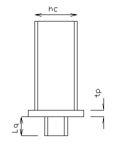
Consider the figure.
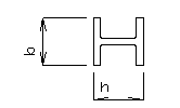
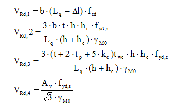
The design shear resistance for I shaped shear iron is given by the minimum of the following shear resistance :
The following formulas are used :
with
|
fcd |
the design value of the concrete cylinder compressive strength of the concrete |
|
Lq |
the length of shear iron |
|
b |
the width of the shear iron |
|
h |
the height of the shear iron |
|
t |
the flange thickness of the shear iron |
|
hc |
the height of column |
|
fyd,s |
the yield strength of the shear iron |
|
fyd,c |
the yield strength of the column |
|
γM0 |
the partial safety factor |
|
tp |
the thickness of baseplate |
|
kc |
1.4 awc |
|
awc |
the weld size for column web/base plate |
|
Av |
the shear area of shear iron |
|
twc |
the web thickness of the column |
|
Δl |
30 mm |
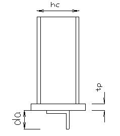
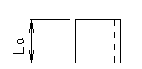
Consider the figure.
The design shear resistance for angle shaped shear iron is given by the minimum of the following shear resistance :
The following formulas are used :
![]()
with
|
fcd |
the design value of the concrete cylinder compressive strength of the concrete |
|
La |
the length of shear iron |
|
da |
the height of the shear iron |
|
t |
the flange thickness of the shear iron |
|
hc |
the height of column |
|
fyd |
the yield strength of the shear iron |
|
γM0 |
the partial safety factor |
|
tp |
the thickness of baseplate |
|
Δl |
30 mm |