![]()
|
||
|
|
||
In this third example, the mapping of arrays is explained. In addition, multiple detailed outputs are used.
As a practical case, concrete Corbel Design is used.
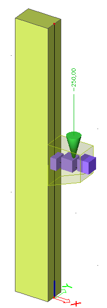
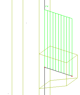
In this example, a column with corbel is modelled. The column has a height of 4m and the corbel is attached in the middle. The column has a rectangular section of 500mm by 300mm. The corbel has a width of 300mm and the height varies from 600mm to 400mm. The corbel has a length of 0,5m. The column base is modelled as fully fixed. All members are manufactured in C30/37 according to EC-EN.
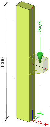
One load case is defined, a point load of 250 kN acting as design load on the corbel. This load is applied at the mid-length position of the corbel.
The check will be done according to the Excel file “Excel_Example_3.xls”
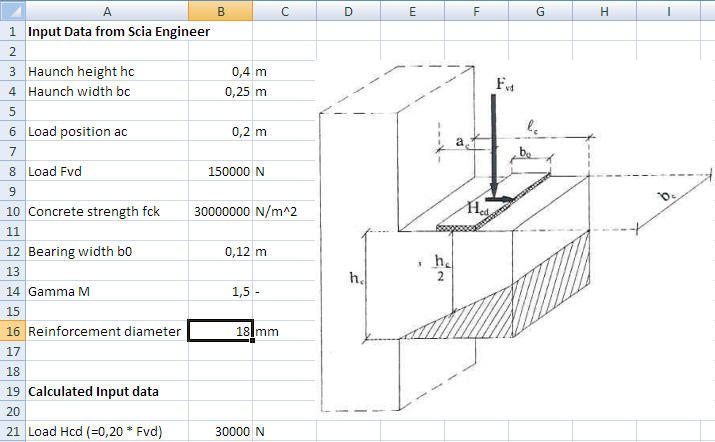
The Excel file contains two worksheets. On the sheet ‘Input’ the input data are set:
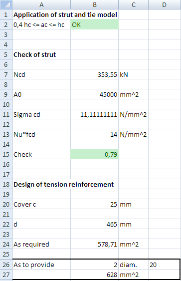
The sheet ‘Check’ shows the check and reinforcement design:
In addition to the default properties of SCIA Engineer, the following user defined parameters will have to be defined: the bearing width b0, the safety factor Gamma M and the reinforcement diameter.
Using the input data, the Excel file generates two types of output.
First the compression strut is being checked and second the required tension reinforcement is determined.
In the Excel file, all cells to which data has to be mapped and from which data is read have been given a name. This allows for a very easy definition of the mapping since these same names will be available in the mapping dialog of SCIA Engineer.
The calculation is a simplification based on the book “Reinforced Concrete, Design following NBN B15-002 (1999), Academia Press, 2001.”
The first step is to activate the functionality External application checks on the Functionality tab in the Project Data.
In the second step, User Defined Additional Data will be defined.
Through Tools > User defined AddData the User Defined Additional Data Library can be opened.
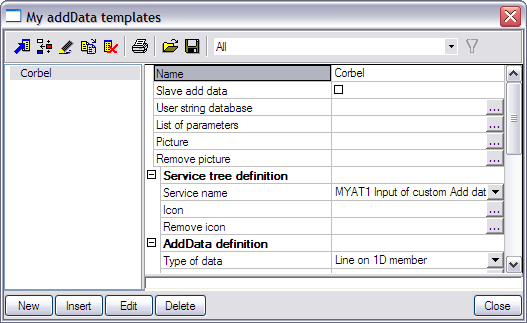
The Name of the additional data is changed to ‘Corbel’.
Only one type of additional data will be defined here and as such the check-box Slave add data is left unchecked.
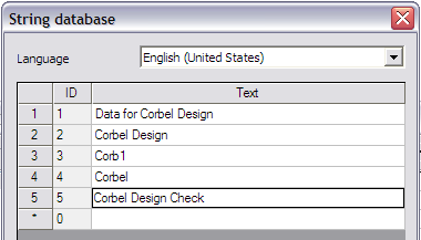
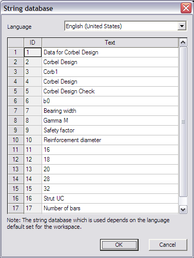
In the User string database the required strings are defined for the definition of the additional data.
Since in this example Corbel Design is being illustrated the strings are modified as follows:
|
Type for which the string is used |
Default string |
String used in this example |
|---|---|---|
|
Service name |
MYAT1 Input of custom add data |
Data for Corbel Design |
|
Type name |
MYAT1 Custom defined add data |
Corbel Design |
|
Short name |
MYAT1 MADI |
Corb1 |
|
Description |
MYAT1 Description |
Corbel |
|
Name of check |
MYAT1 Custom check |
Corbel Design Check |
The necessary strings for the definition of the data are inputted and in the next step the parameters can be defined.
In this example, the mapping will concern of default SCIA Engineer data (Cross-section dimensions, material properties and loading properties) as well as user defined parameters.
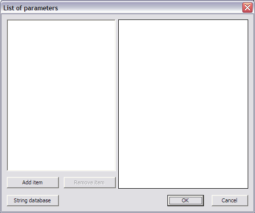
The user defined parameters can be defined through List of parameters.

First, two numerical parameters will be defined, the bearing width and the safety factor:
|
Parameter |
Type |
Default value |
|---|---|---|
|
Bearing width b0 |
Number |
100 mm |
|
Safety factor Gamma M |
Number |
1,5 |
In addition, a combo-box will be defined from which the user can select the reinforcement diameter:
|
Parameter |
Type |
Combo-box lines |
|---|---|---|
|
Reinforcement diameter |
Combo-box |
16 18 20 28 32 |
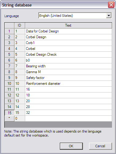
Through the button String database the text string database can be directly accessed. This allows a quick input of the strings required for the parameters.
For this example the following strings are added:
|
Strings used in this example |
|---|
|
b0 |
|
Bearing width |
|
Gamma M |
|
Safety factor |
|
Reinforcement diameter |
|
16 |
|
18 |
|
20 |
|
28 |
|
32 |
Through the button Add item the first parameter, the safety factor Gamma M, is added.
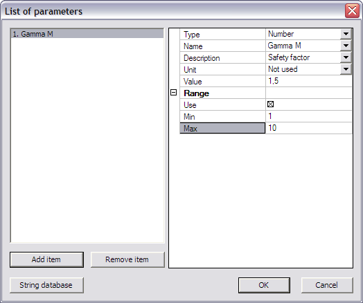
The Type field is set to ‘Number’.
In the Name and Description fields the respective strings can be chosen from the string database, in this case ‘Gamma M’ and ‘Safety factor’.
For this parameter no Unit is used.
The default Value of the parameter is set to ‘1,5’.
In addition, a Range is set to make sure the input is only allowed between a minimum of ‘1’ and a maximum of ‘10’.
In exactly the same way using the button Add item the second parameter, the Bearing width b0, is added.
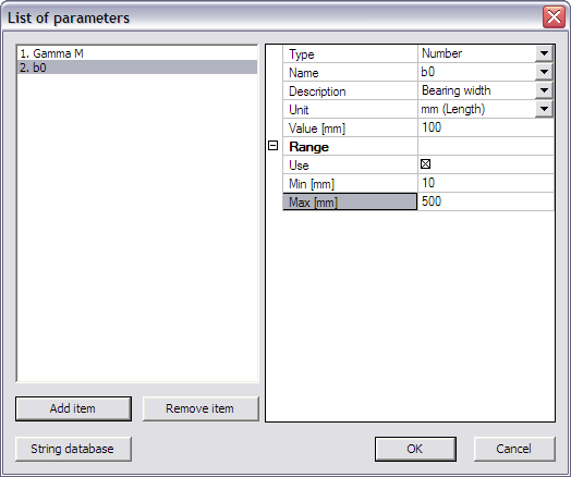
The Type field is set to ‘Number’.
In the Name and Description fields the respective strings can be chosen from the string database, in this case ‘b0’ and ‘Bearing width’.
For this parameter the Unit is set to ‘mm (Length)’.
The default Value of the parameter is set to ‘100’ mm.
In addition, a Range is set to make sure the input is only allowed between a minimum of ‘10’ mm and a maximum of ‘500’ mm.
Using the button Add item the final parameter, the Reinforcement diameter, is added.
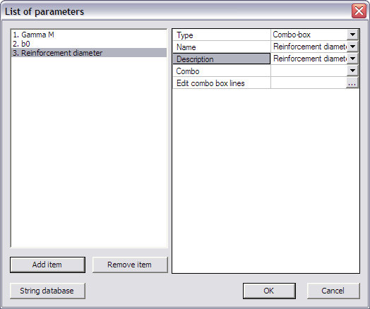
The Type field is set to ‘Combo-box’.
For both the Name and Description fields the string ‘Reinforcement diameter’ is set.
Next, the lines in the combo-box are defined through the edit button Edit combo box lines.
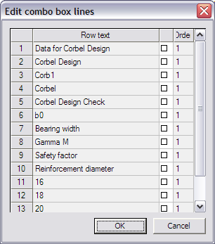
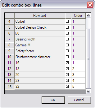
The diameters inputted in the string database are selected and in the Order column the numbers ‘1’, ‘2’, ‘3’, ‘4’ and ‘5’ are inputted.
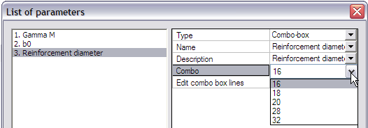
When closing this dialog, the Combo item in the List of Parameters dialog shows how the combo-box will look like.
The required parameters are now defined and the dialog can be closed.
To clarify the use of the additional data and the defined parameters a picture can be added using the Picture button.
In this example the picture Excel_Example_3_Picture.bmp will be used.
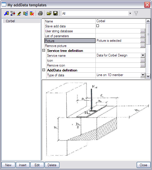
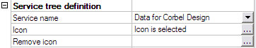
In the next step the Service Tree is defined through the group Service tree definition.
The Service name is taken automatically from the text string database.
To clarify the Service name, an icon can be added using the Icon button.
In this example the icon Excel_Example_3_Icon.bmp will be used.
Using the data from the previous steps, the additional data can now be defined in the group AddData definition.
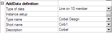
Since the Corbel Design concerns the ‘full’ corbel, the check will be executed on the full length of the corbel. Therefore the field Type of data is set to ‘Line on 1D member’.
The Type name, Short name and Description are taken automatically from the text string database.
To get an overview of all the data entered in the previous steps the button Instance Setup is used.
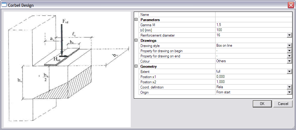
The Parameters group shows the user defined parameters specified in Step 2.3.
In the Drawings group, the Drawing style is set to ‘Box on line’. For the Colour field ‘Thermal load’ is chosen.
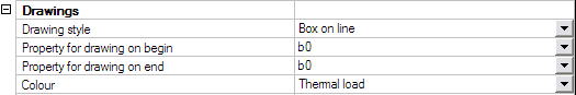
In addition, the Bearing width ‘b0’ is set as Property for drawing on begin/end. The Drawing style will thus change in function of the value of b0.
With this the additional data itself is defined and the dialog can be closed.
In the group Check data the necessary data for the check itself can now be defined.
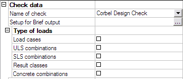
The Name of check is taken automatically from the text string database.
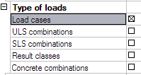
The Type of loads group allows to specify which load types will be available for the check. Only the selected items will be available when executing the check.
Since in this example only one load case was defined, the design loading for the corbel, only the option ‘Load cases’ will be activated.
The final item for defining the check is the Setup for Brief output where the output parameters have to be defined.
For this example, two output parameters will be defined: the unity check value for the strut and the number of required reinforcement bars.
|
Parameter |
Unit |
|---|---|
|
Strut UC |
- |
|
Number of bars |
Not used |
First of all, through the button String database the text string database is accessed to define the required strings. For this example the following strings are added:
|
Strings used in this example |
|---|
|
Strut UC |
|
Number of bars |
When the strings are defined, the first parameter is added through the button Add item.
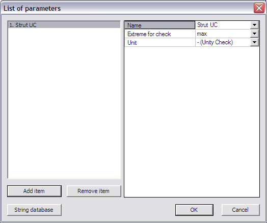
In the Name field the ‘Strut UC’ string is chosen from the string database.
The Extreme for check is left on ‘max’ since the maximal unity check value is extreme in this case.
Since it concerns a unity check, the Unit field is left on ‘– (Unity Check)’.
Again using the button Add item the second parameter is added.
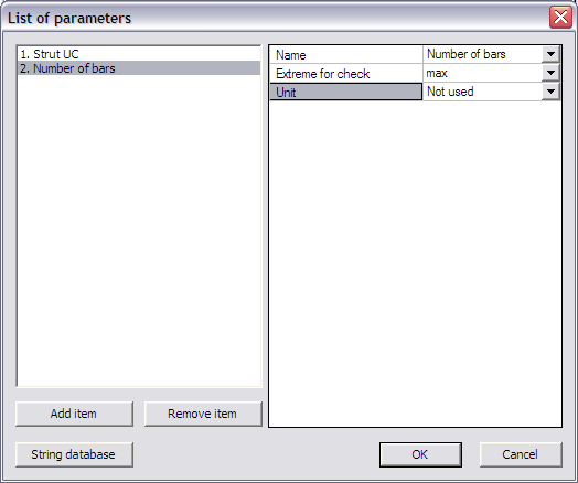
In the Name field the ‘Number of bars’ string is chosen from the string database.
The Extreme for check is left on ‘max’.
For this parameter no unit is required so the Unit field is set to ‘Not used’.
The check and output parameters have now been defined so in the next step the link can be set.
In the External link data group the Type of external link allows to specify which external application will be used.
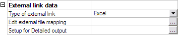
In this example the link is made with Excel and thus ‘Excel’ is chosen.
All preparation has now been done, what remains is the most important step of the process: defining the actual mapping between properties and parameters of SCIA Engineer and the data fields (i.e. Excel cells) of the external application.
Through the button Edit external file mapping the mapping dialog is opened.
In this example, the Excel file contains two worksheets. On the sheet ‘Input’ the input data from SCIA Engineer are set:
The sheet ‘Check’ shows the check and reinforcement design:
In this example, cross-section properties have to be sent to Excel. In the document, it can be seen how the dimensions of a rectangular concrete section are defined:
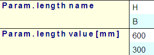
More specifically, the dimensions are located within the Param. length value array. This implies that, when this data is mapped to Excel, two cells will be filled since the array contains two items.
Array mapping concern a very convenient way to map multiple values. Only the starting cell and the direction of the array (horizontal or vertical) need to be specified.
As specified in the introduction of this example, in the Excel file, all cells to which data has to be mapped and from which data is read have been given a name. These named cells can now be used in the Cell address field instead of manually typing the cell number.
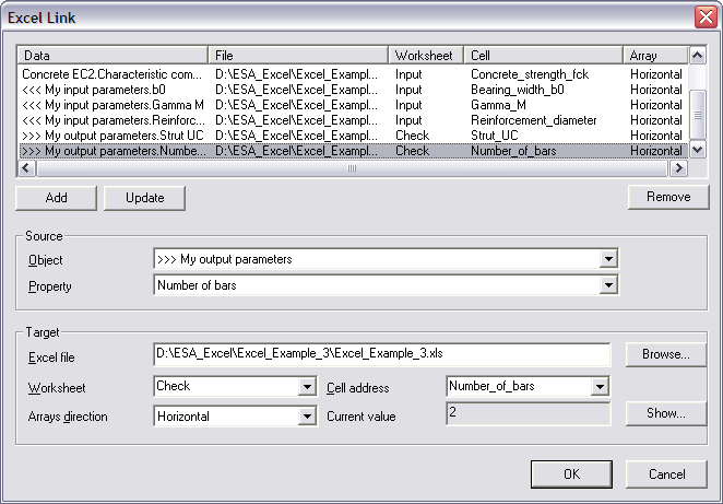
The following table shows which properties should be mapped to which cells:
|
Object |
Property |
Worksheet |
Named Cell (Address) |
|---|---|---|---|
|
Cross-Sections |
Param. length value (Parameters) |
Input |
Cross-Section_Parameters (B3) |
|
Position x (Geometry) |
Input |
Load_position_ac (B6) |
|
|
Point force on beam |
Value - F |
Input |
Load_Fvd (B8) |
|
Concrete EC2 |
Characteristic compressive cylinder strength [28] (Fck) (EC2) |
Input |
Concrete_strength_fck (B10) |
|
<<< My input parameters |
b0 |
Input |
Bearing_width_b0 (B12) |
|
<<< My input parameters |
Gamma M |
Input |
Gamma_M (B14) |
|
<<< My input parameters |
Reinforcement diameter |
Input |
Reinforcement_diameter (B16) |
|
>>> My output parameters |
Strut UC |
Check |
Strut_UC (B15) |
|
>>> My output parameters |
Number of bars |
Check |
Number_of_bars (B26) |
The Object ‘Concrete EC2’ exists twice, once for EC-ENV and once for EC-EN. The Property ‘Characteristic compressive cylinder strength [28] (Fck) (EC2)’ can be found in the EC-EN Object.
For the position of the loading, the property Position x is used. It is important to note that this position is dependent on the coordinate definition of the point load: this can either be absolute or relative. For this example, the Position x has been inputted as absolute. The Excel file could be modified with a test to see if the coordinate definition is absolute or relative and modify the Position x value accordingly.
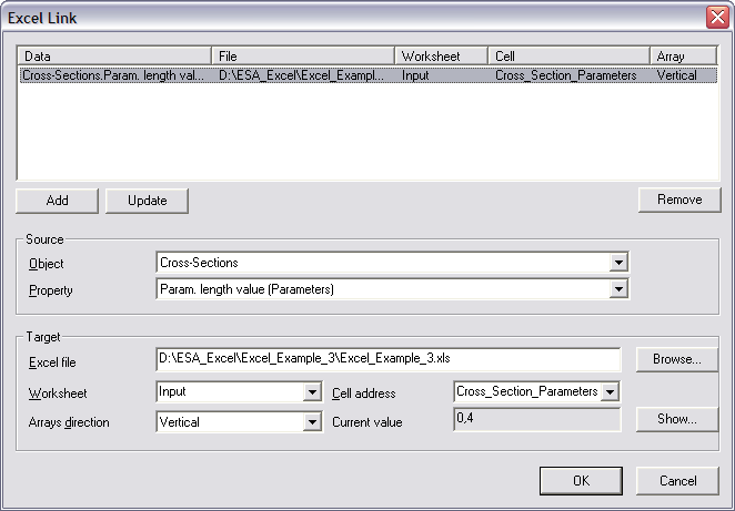
The mapping of the first property, the cross-section dimensions, is thus done as follows:
The Object field is set to ‘Cross-sections’.
In the Property field ‘Param. length value (Parameters)’ can then be chosen.
Using the Browse button, the file Excel_Example_3.xls is searched.
After the file has been specified, the Worksheet field contains a list of all sheets. This field is set to ‘Input’.
The Arrays direction is set to ‘Vertical’ since this array contains two values which need to be positioned in a vertical column.
Finally, in the field Cell address the named cell ‘Cross-Section_Parameters’ is chosen using the combo-box. Automatically the Current value field will show the current content of the cell, in this case 0,4. During the mapping, the first parameter of the array, in this case the value of the height, will be mapped to cell B3. The second parameter of the array, in this case the value of the width, will be mapped to cell B4.
When all input has been done, this mapping is added to the table using the Add button.
In the same way, all other parameters can be mapped using the above table. For the other parameters, the array direction is left on horizontal.
All parameters are now mapped to Excel. The final step left for the definition of the additional data is specifying a Detailed output.
In Step 2.7 the parameters for the Brief output have been defined. These parameters will be used for the check. In addition, a Detailed output can also be specified to show an in-depth overview of the check.
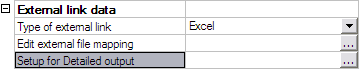
By clicking on Setup for Detailed output, the Detailed output dialog is opened.
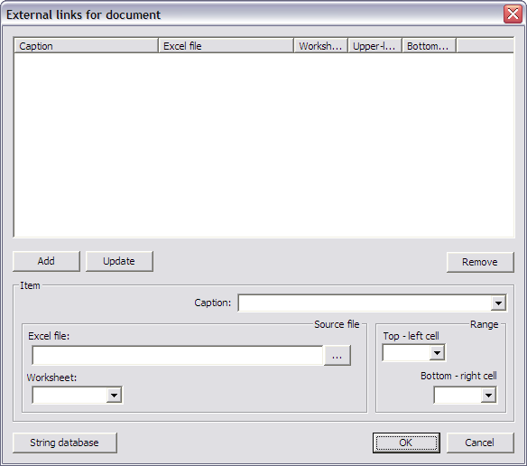
In this example, two ranges will be defined. One which shows the input data and one which shows the results. For ease of reference, here also Named cells have been defined in the Excel file.
|
Caption |
Worksheet |
Top – left cell |
Bottom – right cell |
|---|---|---|---|
|
Input Data |
Input |
Input_Top_Left |
Input_Bottom_Right |
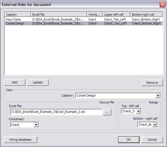
|
Corbel Design |
Check |
Check_Top_Left |
Check _Bottom_Right |
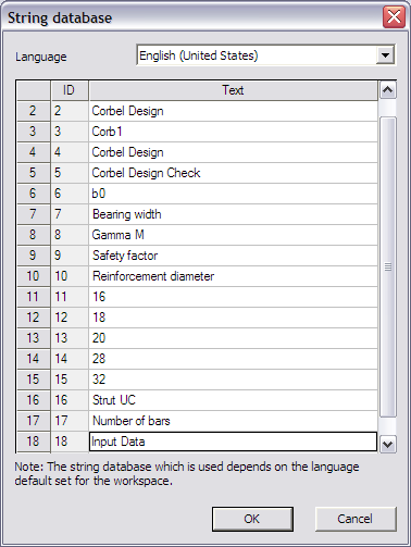
Through the button String database the text string database can be directly accessed. For this example the following string is added:
|
Strings used in this example |
|---|
|
Input Data |
All required strings are no available so the ranges can be defined.
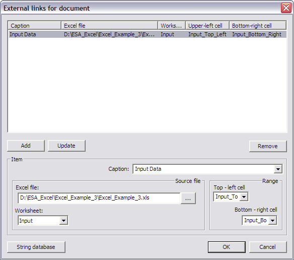
In the Caption field the string ‘Input Data’ is chosen.
In the Excel file field the file Excel_Example_3.xls is searched using the browse button.
The Worksheet field is set to ‘Input’.
In the Range group the Top - left cell is set as ‘Input_Top_Left’ and the Bottom - right cell as ‘Input_Bottom_Right’.
When all input has been done, the data is added to the table using the Add button.
In the same way, using the above table the second range is added.
With this final step, the User Defined Additional Data has been fully inputted and the User Defined Additional Data Library can be closed.
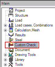
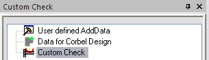
After closing the User Defined Additional Data Library a new service will be shown in the SCIA Engineer tree: Custom Check.
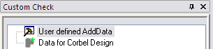
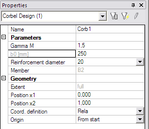
The additional data which was defined in Step 2, can now be inputted on the member. When double clicking on Data for Corbel Design the dialog with the properties of the data is displayed:
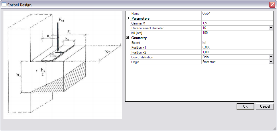
The Parameters group holds the user defined parameters of Step 2.3 with their default values. In this case the safety factor ‘Gamma M’, the Bearing width ‘b0’ and the combo-box ‘Reinforcement diameter’.
The default values of the dialog are confirmed with [OK] and the data is inputted on the corbel.
Through the View Parameter settings, the Style / Rendering of the additional data can be specified on the Misc. tab. This works in the same way as for any other type of additional data (loads, supports …).
In case the additional data is too large or too small, the scale multiplier ‘User defined AddData’ in the default SCIA Engineer Scales manager.
The data has now been inputted and in the next step the check can be executed.
In Step 2 the additional data has been defined including the definition of the check, the mapping to Excel… In Step 3 the additional data has been inputted. What is left is the execution of the check.
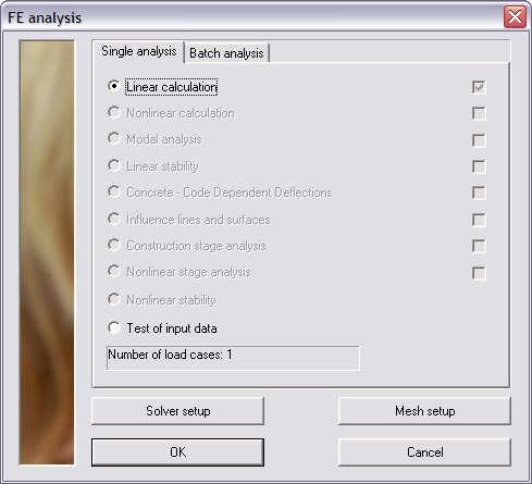
First of all the linear analysis is launched.
When user defined additional data was inputted and the analysis has been executed, the Custom Check service will show a new item: Custom Check.
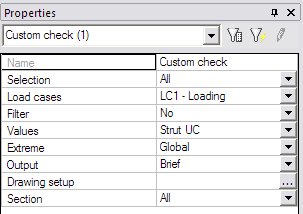
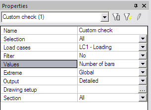
In the property window of the check, the Values field is set to ‘Strut UC’ and the Refresh action button is pressed to execute the check.
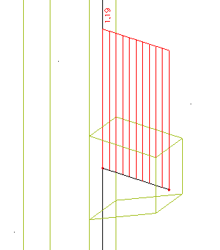
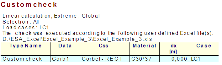
The following check result is shown on screen:
When pressing the Preview action button, the Brief preview shows the following:
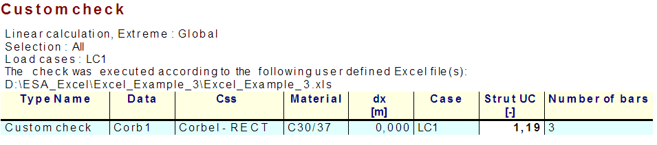
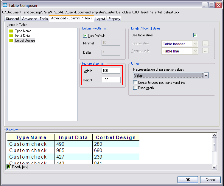
Using the table composer, both the Strut UC and number of bars can be added to the output as specified in the previous examples. After refreshing the following preview is shown:
Next, the Detailed output is examined. The Output field is set to ‘Detailed’ and the Refresh action button is pressed.
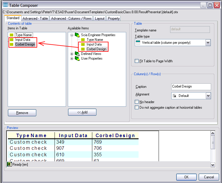
Here also, the newly created output table needs to be added to the output using the table composer.
Both ranges defined in step 2.10 can now be added to the output.
In addition, the size of these tables can be set to 100mm by 100mm.
After refreshing, the following output is shown:
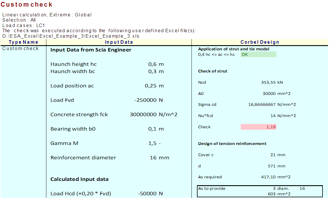
The output shows the array mapping of the haunch dimensions hc and bc. In addition the conditional formatting used in the Excel file is nicely shown in the SCIA Engineer output.
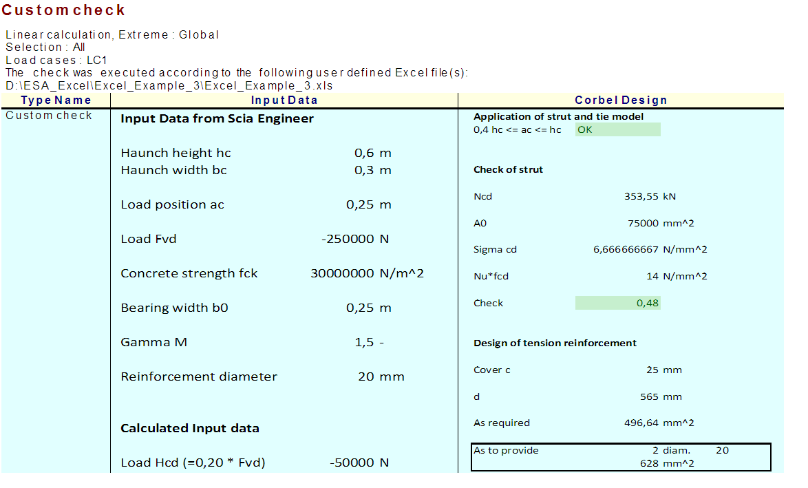
In a next step, the additional data is selected and some changes are made to the input: the bearing width b0 is increased to 250 mm and the reinforcement diameter is set to 20.
After refreshing these changes are shown in the detailed output:
Previously the Strut unity check was displayed on screen. In the same way the number of bars can be shown by changing the Values field to ‘Number of bars’.
After refreshing, the following result is shown on screen:
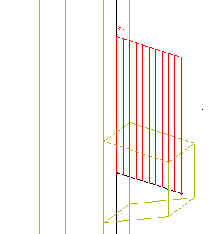
By default this graphical result is shown in red since the result is greater than 1,00. However, using the default Drawing Setup of SCIA Engineer, this setting can be changed as in any other check service.
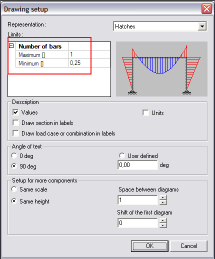
The default minimum and maximum limits for check results are 0,25 and 1,00. For the Number of bars, the minimum can be set to 1 and the maximum to for example 10.
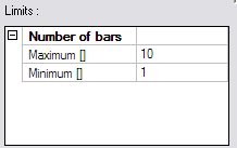
After refreshing, the graphical result is now shown in green since the value is between the minimum and maximum limits.
If required, this additional data can be saved into a database for future use as illustrated in Example 1.