![]()
|
||
|
|
||
During an earthquake, the subsoil bearing a structure moves. The structure tries to follow this movement and as a result, the masses in the structure begin to move. Subsequently, these masses subject the structure to inertial forces.
The method which is implemented in SCIA Engineer is based on modal superposition. The user defines the loading by spectrums in the 3 global directions X, Y and Z (in a 3d model).The program computes the modal deformation and modal forces.
Two methods are implemented to consider the missing mass into the seismic analysis.
Depending on the selected Modal combination method, the modal results are summed to obtain the final results.
The results (deformations, internal forces, reactions) are displayed on the standard way. A dedicated menu was implemented in order the display the modal and summed deformation and acceleration.
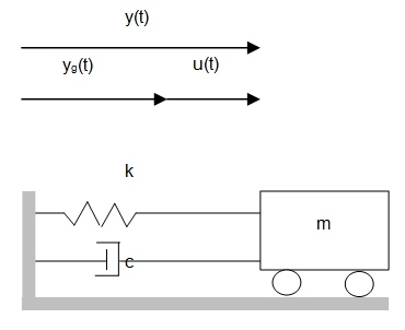
Consider the SDOD system shown in figure bellow which illustrates the displacement of a system that is submitted to a ground motion.
Where:
yg(t) : is the ground displacement,
y(t) : is the total displacement of the mass
u(t) : is the relative displacement of the mass
The total displacement can thus be expressed as follows:
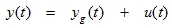
|
(5.1) |
Since yg is assumed to be harmonic, it can be written as:
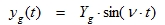
|
(5.2) |
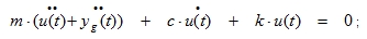
The equilibrium equation of motion can now be written as:
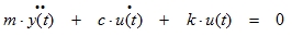
|
(5.3) |
Since the inertia force is related to the total displacement (y) of the mass and the damping and spring reactions are related to the relative displacements (u) of the mass.
When (5.1) is substituted in (5.3) the following is obtained:
|
or

|
(5.4) |
This equation is known as the General Seismic Equation of Motion. This equation can be used to illustrate the behaviour of structures that are loaded with a seismic load:
Substituting (5.2) in (5.4) gives the following:

|
This equation can be compared with equation (3.2) of the chapter Harmonic loading. As a conclusion, the ground motion can also be replaced by an external harmonic force with amplitude:
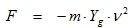
|
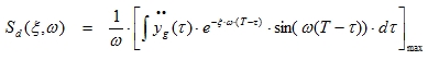
When a structure has to be designed to withstand an earthquake, spectral analysis is often used because the earthquake loading is given under the form of a response spectrum. This response spectrum can be either a displacement or a velocity or an acceleration spectrum. The relation of an earthquake given by an acceleration time history and the corresponding spectrum is given by:
|
(5.5) |
With:
 : Ground acceleration in function of time
ξ: Damping factor
T: The period 2π/ω
The integral between the square brackets is known as the Duhamel integral. This integral is the solution of the differential equation (5.4).
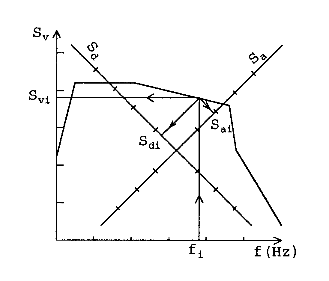
Instead of Sd (displacement response spectrum), Sv (velocity response spectrum) or Sa (acceleration response spectrum) can be used. These spectra are related by ω :
Sa = ω.Sv = ω².Sd(5.6)
The three spectra are normally given on the same figure, using different scale-axes. (See picture of spectral density bellow)
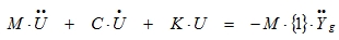
For MDOF (Multiple Degree Of Freedom) systems, equation (5.4) can be written in matrix notation as a set of coupled differential equations:
|
(5.7) |
The matrix {1} is used to indicate the direction of the earthquake. For a two-dimensional structure (three degrees of freedom) with an earthquake that acts in the x-direction, the matrix is a sequence like {1,0,0,1,0,0,1,0,0,…}
The resulting set of coupled differential equations is reduced to a set of uncoupled differential equation by a transformation U = Z.Q, where Z is a subset of Φ (the eigenvectors) and Q is a vector, which is time-dependent.

|
or

|
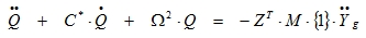
This can be simplified to a set of uncoupled differential equations:
|
(5.8) |
Where is a diagonal matrix containing terms like
  .
.
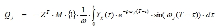
Each equation j has a solution of the form:
|
(5.9) |
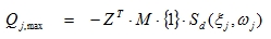
To obtain the maximum displacements, the displacement response spectrum Sd of equation (5.5) can be substituted:
|
(5.10) |
And:
|
(5.1) |
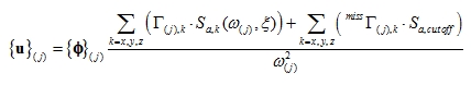
Or:
|
(5.11) |
Where  is known as the modal participation factor.
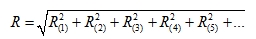
One obtains in each node a value of (Uj)max, j=1,m (m<n). The maximal global displacement is the sum of the absolute values of the displacements. Often, the RMS (root mean square) is used as maximal displacement:
Umax = ÖΣ(Uj)²max (5.12)
The SCIA Engineer program supports 3 combination methods:
SRSS (Square Root of Sum of Squares)
CQC(Complete Quadratic Combination)
MAX (max method)
The detail is described in next chapter, “Modal combination method”
Modal combination methods are used to calculate the response R of a seismic analysis. The term "response" (R) refers to the results obtained by a seismic analysis, i.e. displacements, velocities, accelerations, member forces and stresses.
Because the differential equations were uncoupled, a result will be obtained for each mode j.
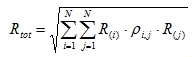
To obtain the global response Rtot of the structure, the individual modal responses R(j)have to be combined.
The modal combination methods that are used in SCIA Engineer are:
|
(5.13) |
With:
R(j) : The response of mode j
|
(5.14) |
With:
R(i), R(j): The response of mode i and j
ρi,j: Modal Cross Correlation coefficients.
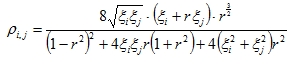
|
(5.15) |

ξi, ξj: Damping ratio for mode i and j.
This method is based on both modal frequency and modal damping. The CQC-method requires the input a Damping Spectrum.
Let’s remark that the defined spectrum is overruled, in case non-uniform damping method is used. See for detail at chapter “damping”.
|
(5.16) |
With:
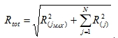
R(j) : The response of mode j
R(jMAX) : The maximum response of all modes
Remarks: the short info at the seismic load case displays what is selected. Following format is used:
Short info = {Modal combination method}& “/” &{Coeff X} & “X” & “;” {Coeff Y} & “Y” & “;” {Coeff Z} & “Z” & “/”{acceleration coefficient}
Where
| {Modal combination method}: | SRSS or CQC or MAX |
| {coeff X, Y, Z}: | The coefficient of spectrum X, Y and Z |
| X,Y, Z: | The spectrum X in the global X |
| {acceleration coefficient}: | The assumed acceleration coefficient: |
The mass can be taken in tree ways in the seismic analysis. In the menu “General seismic load”, the group “Mass in the analysis” contains 3 options:
Participation mass only
Missing mass in modes
Residual mode
In case “Participation mass only” is selected, then only the participation mass from the selected number of modes is taken into account in the seismic analysis.
In case “Missing mass in modes” is selected, then the missing mass is assigned to the known modes (E.G. modes selected by the user in the analysis).
In case “Residual mode” is selected, then the missing mass is taken in the seismic analysis as an extra mode which represents the weight of the missing mass. The modal result of this mode is computed by a static equivalent load case.
Remark: The used method is displayed in the linear calculation protocol
The aim of the method is to smooth the missing mass to the known modes and then compute modal deformations and then the modal forces. Afterwards its summed depending the selected rule SRSS, CQC, MAX
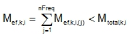
Missing mass is assigned to known eigenmodes. Suppose we have determined k eigenmodes, where
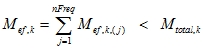
|
(5.17) |
k - is direction
Mef,k - is effective mass
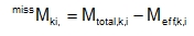
Missing mass can now be written as
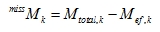
|
(5.18) |
Ration between effective mass and missing mass is

|
(5.19) |
Now we can write these formulas
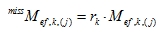
|
|
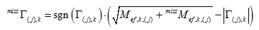
|
(5.20) |
|
Then(5.21)
|
The aim of the method is to evaluate the missing mass as an extra mode which is computed as an equivalent static load case. The static load represents the weight of the missing mass under the cut-off acceleration. Afterwards its summed depending the selected rule SRSS, CQC, MAX
The missing mass is computed in each node as difference between total mass and effective mass.
|
(5.22) |
k - is direction
i - is node
j - is mode
Mef,k,i - is effective mass, direction k, node i
Missing mass can now be written as
|
(5.23) |
A static load case of weight in computed, which is handled as a “real” mode.
For each direction k, selected in the “General seismic load” interface, the amplitude of static load is computed as:
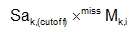
|
(5.24) |
Sak is acceleration of “cut off” frequency in direction k (i.e. last calculated frequency)
MissMk,i missing mass in direction k, node i
Afterwards, the extra mode is summed depending the selected rule SRSS, CQC, MAX
Remark1: In case of CQC, we do not assume correlation with the other modes (i.e. absolute value is added)
Remark2: The cut off frequency is the frequency of the latest modes in the analysis. It is of the responsibility of the user to select the correct number of modes
The aim of the method is to take the sign of the mode in the seismic analysis, which computes by default only positive results.
In menu General seismic load, the user selects for “Signed results”. When the property is "checked", then a combo is displayed wherein the use selects a mode shape. The list items displayed in the combo box are: “default”; 1; 2; ..; N ( N the number of frequencies selected by the user).
The default stays for modes shape with biggest mass participation is used (direction X, Y and Z together). Beside the “default”, the user is allowed to select a mode shape, which will determine the sign of the modal combination.
The tool can be used in the seismic analysis in case SRSS.
Modes are taken together in case the precision is fulfilled
Classic SRSS
|
SRSS with multiple eigen shapes
If
 precision, where precision, where 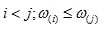 |
Mode (i) and (j) are multiple. Then for example
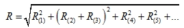
|
(5.25) |
Where mode 2 and 3 are multiple.
In the calculation protocol of SCIA Engineer the intermediate results that were determined while calculating the global effect of a spectral loading can be found.
This paragraph describes the formulas that have been used to determine those intermediate results.
Natural circular frequency and modal shape
|
Mass matrix |
|
|
Mass vector |
|
|
Natural circular frequency of mode shape j |
|
|
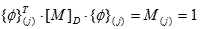
Natural normalized modal shape |
With |
|
Total mass in kth direction |
|
|
Acceleration response spectrum |
|
|
Direction |
k |
|
Total number of directions |
NK |
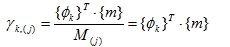
Participation factor of the mode shape j in direction k
|
Participation factor |
|
|
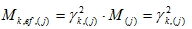
Effective mass |
|
|
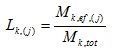
Participation mass ratio |
|
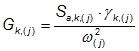
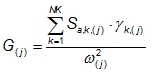
Mode coefficient for mode j
|
Mode coefficient in kth direction |
|
|
Total mode coefficient |
|
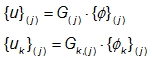
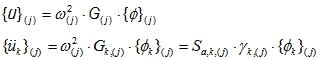
Response of mode shape j
|
Displacement |
|
|
Acceleration |
|
|
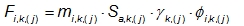
Lateral force in node i for direction k |
|
|
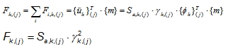
Shear force in direction k |
|
|
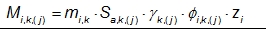
Overturning moment in node i for direction k |
|
|
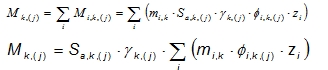
Overturning moment in direction k |
|
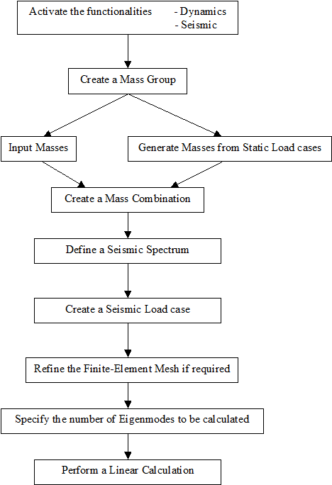
In SCIA Engineer, a Seismic Load can be inputted after creating a Combination of Mass Groups. This implies that the steps used to perform a Free Vibration calculation still apply here and are expanded by the properties of the Seismic Load.
The Design Spectra are defined for a damping ratio of 5%. If the structure has another damping ratio, the spectrum has to be adapted with a damping correction factor η.


 ,
,