Open topic with navigation

First use of Revit link - example
Creating the model in Revit Structure
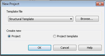
- Start a new project in Revit Structure.
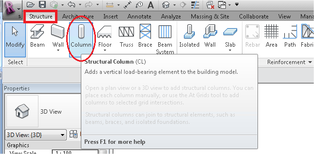
- Start with inputting 2 column (standard Revit families; cross section H-Wide Flange Column: HEA300 and material Steel, 45-345) of 3 meters height at a distance of 4 meters. Then add a beam (same cross-section and material) between the upper ends of the columns.
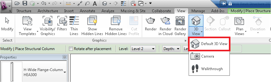
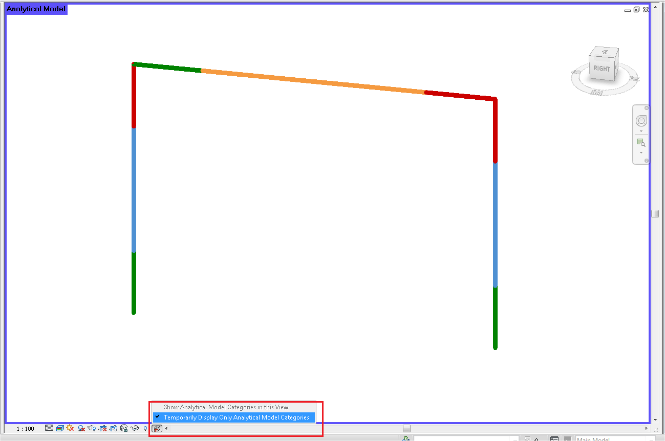
- Now change the view towards the analytical model.
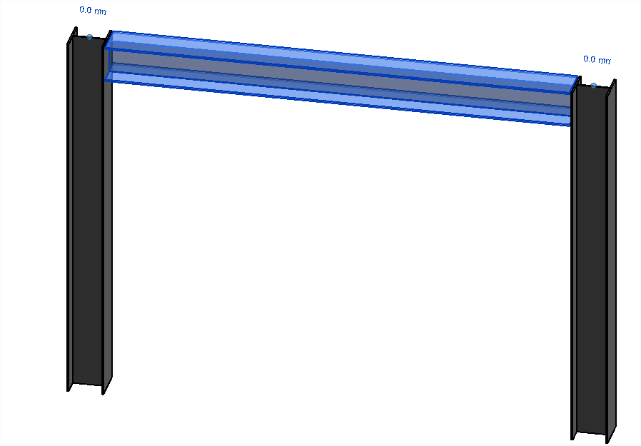
- This is the model that will be transferred by the Revit link. If there is nothing here, then you are not using the correct families. Also if the lines of the columns and the beam do not connect, then you must manually change the analytical model to correct this.
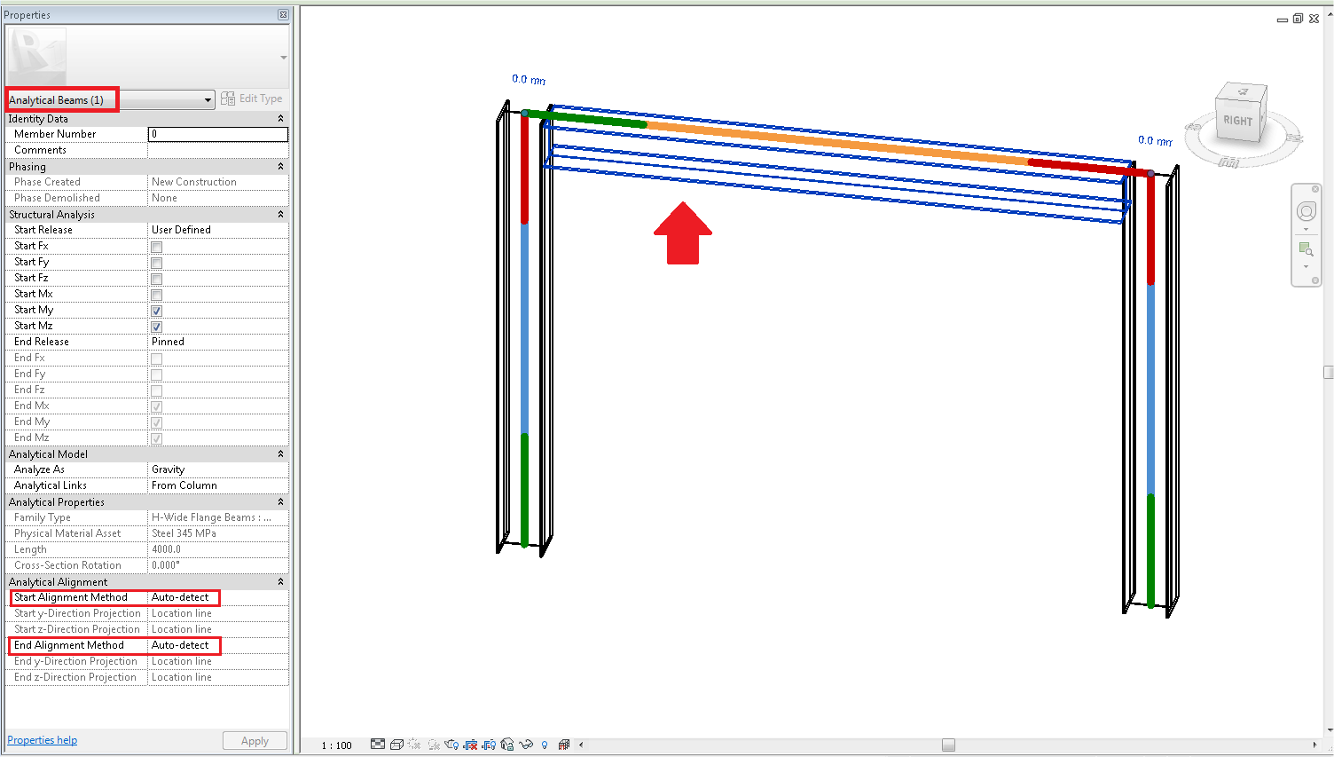
- However, Revit structure is designed to optimally use both analytical models and volumetric models at once (when creating this example, it was also not necessary to correct the analytical model). This can also be seen in the properties of the beams and columns if we look at their ‘analytical’ properties.
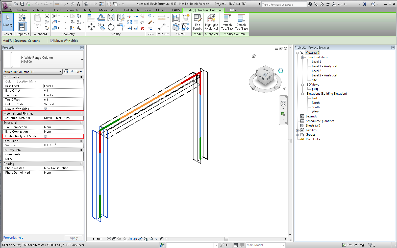
- Also make sure that each element which you want to transfer, has ‘Enable Analytical Model’ activated, and that there is a ‘Structural Material’ indicated for that element. Revit Structure does not require a material for each element, but the Revit link does require that each element that you want to transfer has a material.
- It can be possible that you must still indicate a material. To do this, click on the three dots in the same line as ‘Structural Material’, and choose the desired material.
Using the Revit link
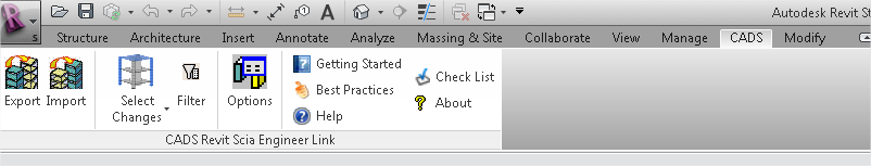
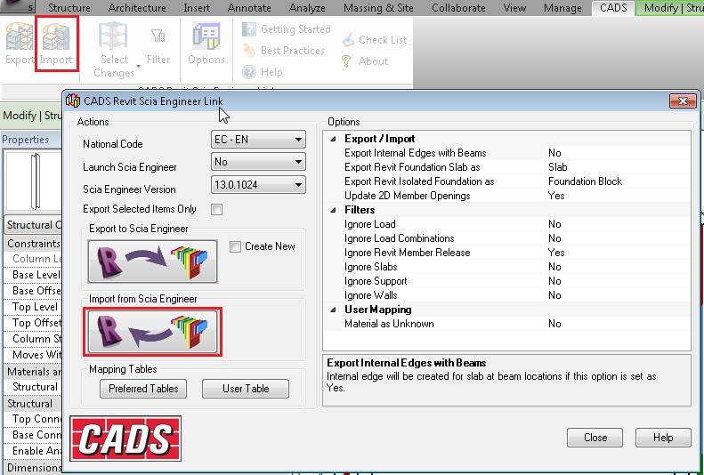
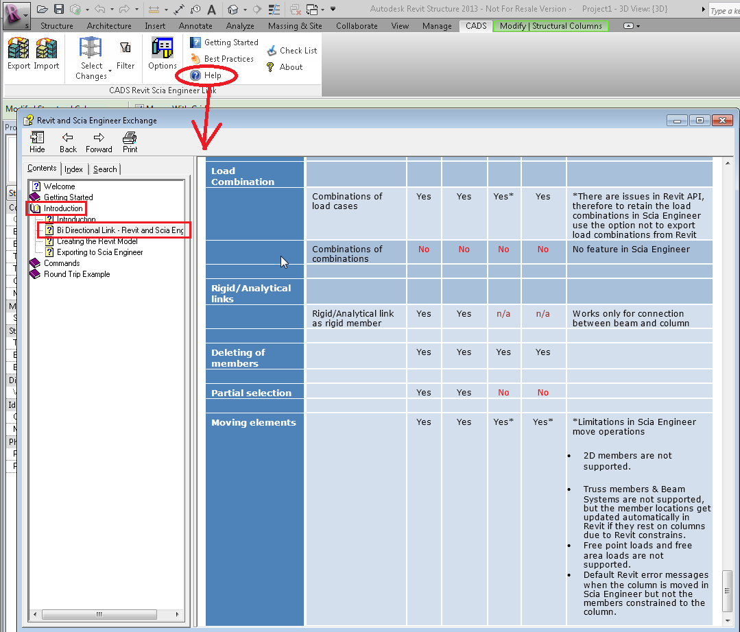
- In Revit Structure, there should be a tab ‘CADS’. This tab is installed by the Revit Structure plug-in (as described in the part ‘Introduction & requirements’). If this tab is not available, then please check if the ‘requirements for Revit structure’ (p.2) have been met.
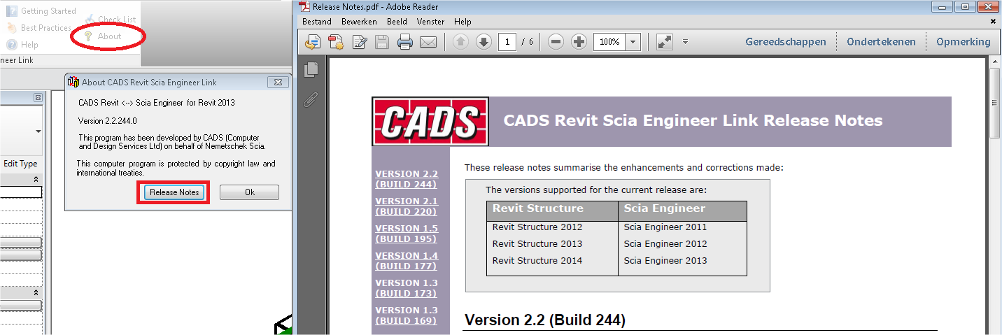
- If you are searching for extra documentation/help, then the options ‘Getting Started’, ‘Best Practices’, ‘Help’ and ‘Check list’ can be of great help to you. Also the option ‘About’ will give you the version of the Revit link, but also the release notes (improvements in the last patch of the Revit link in comparison with the previous one).
- The part described above is just for extra information. Now go to ‘Options’.
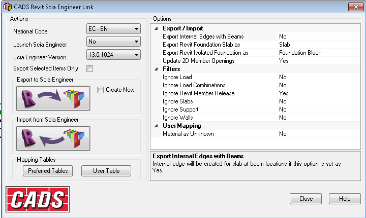
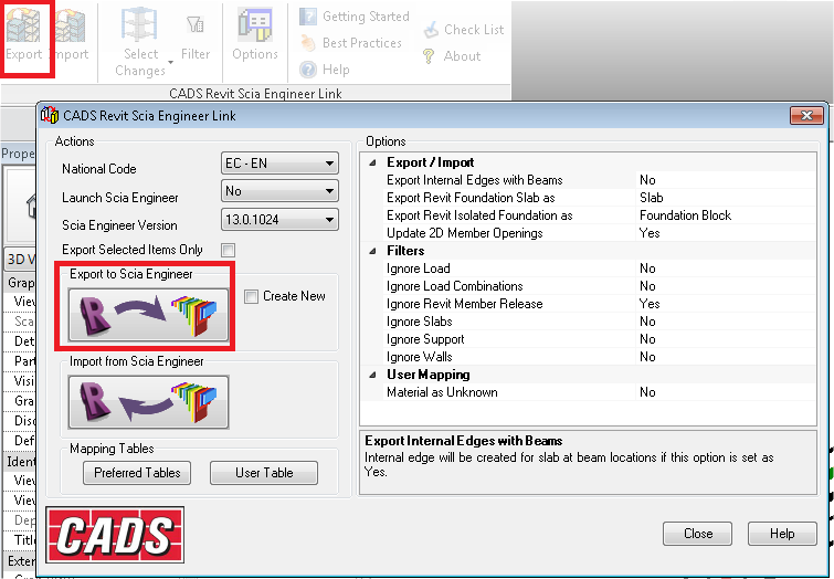
There are several functions which affect what can be transferred to the SCIA Engineer. These functions can be found in the Options dialogue.
- The Revit link exports structural 1D members and 2D members with openings. The supports can be exported as a Foundation blocks or Standard supports.
The Revit link exports the whole or the selected part of the structure from the Revit project.
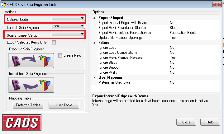
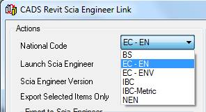
These options give the Revit link the information it needs to execute the transfer. Since this is the first time the Revit link is used, the ‘National Code’ as well as ‘SCIA Engineer Version’ will be blank.
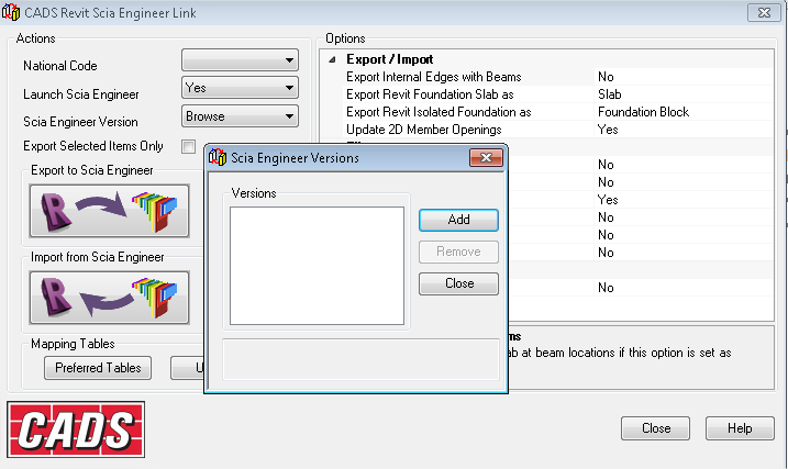
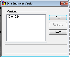
- Click on the box after SCIA Engineer version and choose browse. Now the Revit Link wants you to add the different version of SCIA Engineer which you have installed on the pc. This is why a version of SCIA Engineer also has to be installed on the same pc as Revit Structure. The Revit link uses the installed files to make the link between Revit Structure and SCIA Engineer.
- Choose ‘Add’ and browse to the folder where SCIA Engineer is installed (the Revit link will search for esa.exe in this folder). For 64-bit pc’s, the default location is C:\Program Files (x86)\Scia\Engineer 2013.0\.
After indicating the path, you will see the version of SCIA Engineer in the window. After closing this window, you will also see that ‘National Code’ now has multiple choices available.
- In between the two options, there is ‘Launch SCIA Engineer’. If you chose ‘yes’, then the Revit link assumes that you wish to import and export from SCIA Engineer on this pc. If you chose ‘no’, it will create an .r2s (Revit to Scia) file, which can be imported on the other pc later on in SCIA Engineer (regardless of this option, the transfer will always happen by means of a .R2S file).
- Let us chose ‘no’ for this option (this makes it easier to find the (user) error during tests). Explanation for the other options can be found in the ‘Help’ of the Revit Link (which has been mentioned on the previous page). To completion of this tutorial, I have copied the explanation of the different options to appendix 1.
- Before you are going to export the Revit Structure project to SCIA Engineer, you must save the project first. Then choose the ‘export’ option. Note that the ‘Export’ button under the tab ‘CADS’, or the ‘Export to SCIA Engineer’ button in the options of the tab ‘CADS’ do the exact same thing: create an .R2S file that can be imported in SCIA Engineer.
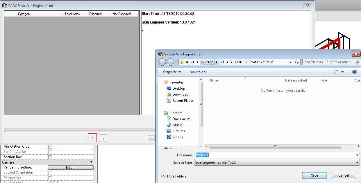
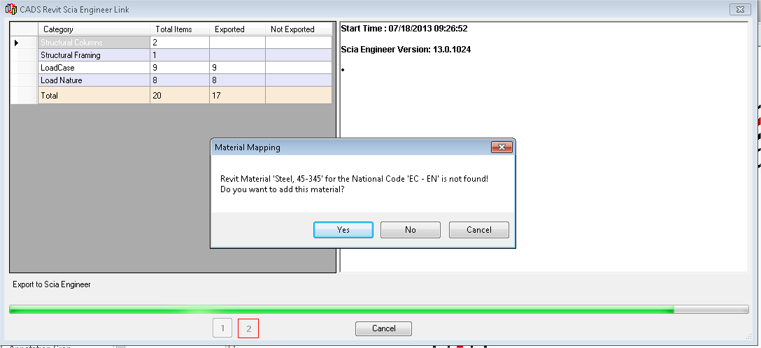
- You will see the ‘CADS Revit SCIA Engineer link’ progress window appear. Here you can see which items (beams, columns, plates, load cases ...) are recognised by the link. It will also ask where to save the .R2S file (which is the file you must import in SCIA Engineer). Save the ‘SCIA Engineer r2s file’ as ‘Project1’ and choose ‘Save’.
- Once the transfer has started, the link will give a message when it does not recognise a certain item. The link is based on names. In this example, the Revit material ‘Steel, 45-345’ cannot automatically be linked to SCIA Engineer. This link is called ‘mapping’, and must be added manually if the link cannot do the mapping automatically.
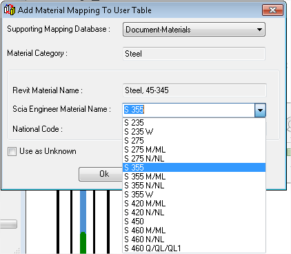
- Click ‘Yes’ and choose the correct ‘SCIA Engineer Material Name’ (for example S355).
There is also an option ‘Use as Unknown’. We strongly advise to NOT use this option. This will generate problems when you are importing the file in SCIA Engineer later on.
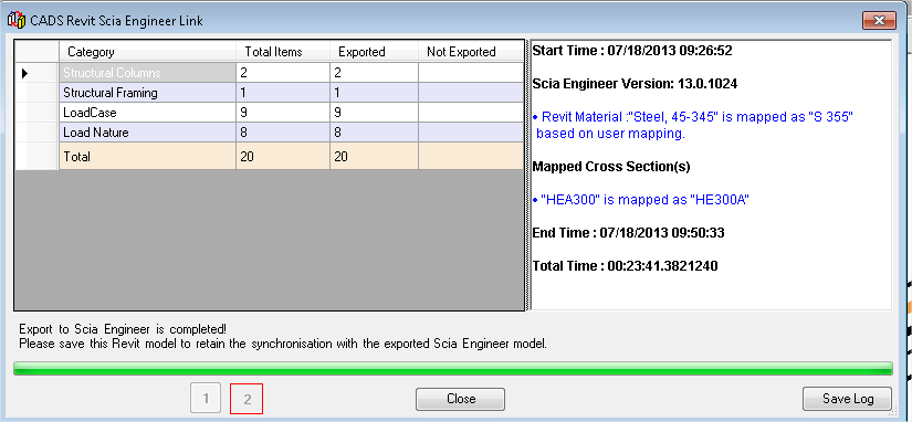
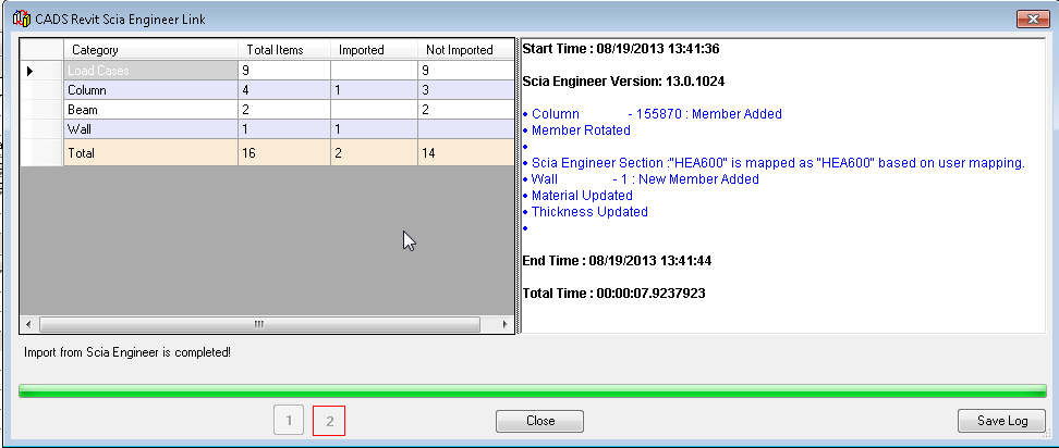
- Once the export is completed, you will be able to see the total number of items recognised for each category, and the amount which has been successfully exported. Not that the separate elements (structural columns and structural framings) must have analytical lines to be recognised.
- On the right side of the window, you will be able to see the log file. This explains how the mapping has been done for the different materials and cross sections.
- Revit Material “Steel, 45-345” is mapped as “S 355” based on user mapping
- “HEA300” is mapped as “HE300A”
This log file can also be saved by using the option ‘Save Log’ (in the bottom right corner of the window).
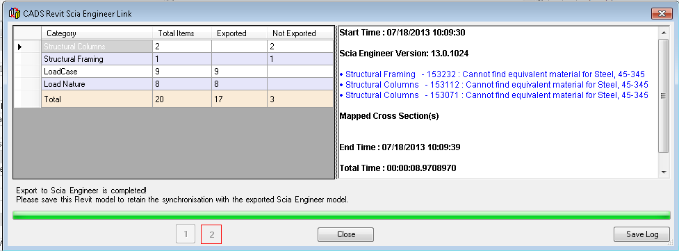
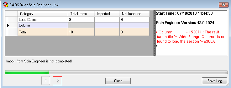
- If we would not have mapped this material (by clicking ‘no’ for the question to add this material), then all elements that used this material, would not have been exported (see image below).
- The log can be saved to the text-file when the export is finished. SCIA Engineer is opened automatically if it is set in the option dialogue and the newly exported structure will be displayed in the model window. If you are doing tests with the Revit link, we advise to keep this option off, and to open SCIA Engineer manually later. The reason for this is to easily identify if the problem is on the the Revit side or on the SCIA Engineer side if there would be a problem configuring the link.
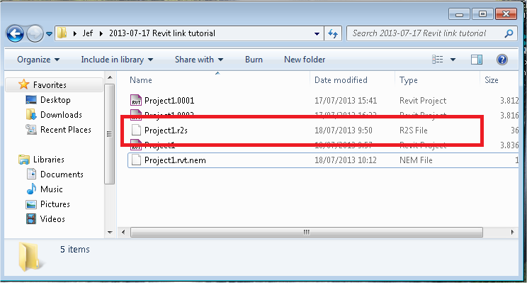
- Now open your Windows explorer, and go to the .R2S file which has been generated by the Revit link. Copy this file to the pc where you wish to import the file in to SCIA Engineer.
Importing in SCIA Engineer
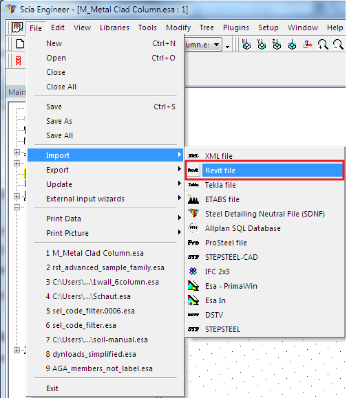
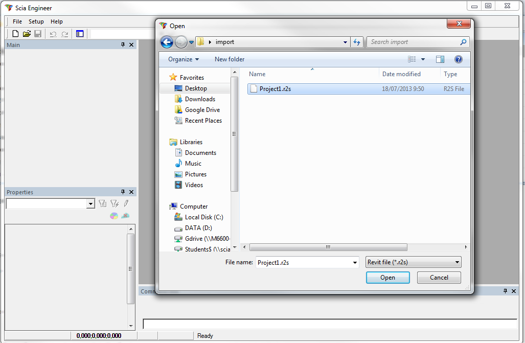
- Open SCIA Engineer, and import the .R2S file:
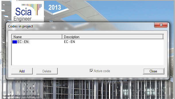
- SCIA Engineer will ask for a code. The .R2S file is mapped to the SCIA Engineer materials for the code that was configured in the Revit Link options (in this case the EC-EN). We will use the EC-EN in SCIA Engineer as well (if necessary, ‘Add’ the correct code). Click ‘close’ if you have the correct code.
- Now you will see the imported items in SCIA Engineer.
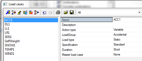
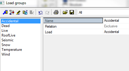
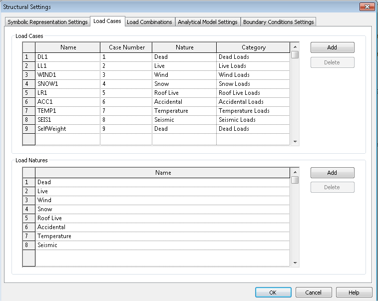
- Under ‘load cases’, you will also find the load cases which have been transferred from Revit Structure to SCIA Engineer. These are the same 9 load cases that you could see being exported by the Revit link (2 pages back). The ‘Load Natures’ from Revit Structure are imported as ‘Load Groups’ in SCIA Engineer.
SCIA Engineer:
Revit structure:
- Now we will change the project in SCIA Engineer, and then export it back to SCIA Engineer. Copy 1 beam and 1 column, and change 1 cross-section to HEA600.
- Exporting from SCIA Engineer
- The file will be saved as an .r2s file again. This time we’ll name it ‘Project1s.r2s’. Be sure to unselect everything in SCIA Engineer first, otherwise only the selection will be exported.
Importing in Revit Structure
- Copy the ‘Project1s.r2s’ file that has just been created to the computer with Revit Structure.
- Open Revit Structure (with an empty project) and go to the ‘CADS’ tab. Choose ‘Import’ (which you can find both in the CADS-tab as in the options dialogue) and select the ‘Project1s.r2s’ file.
- You will see that the ‘HE300A’ from SCIA Engineer is not linked to Revit Structure. This is probably a problem with families that are not loaded properly in Revit Structure. We will solve this by adding the referred family to our Revit link.
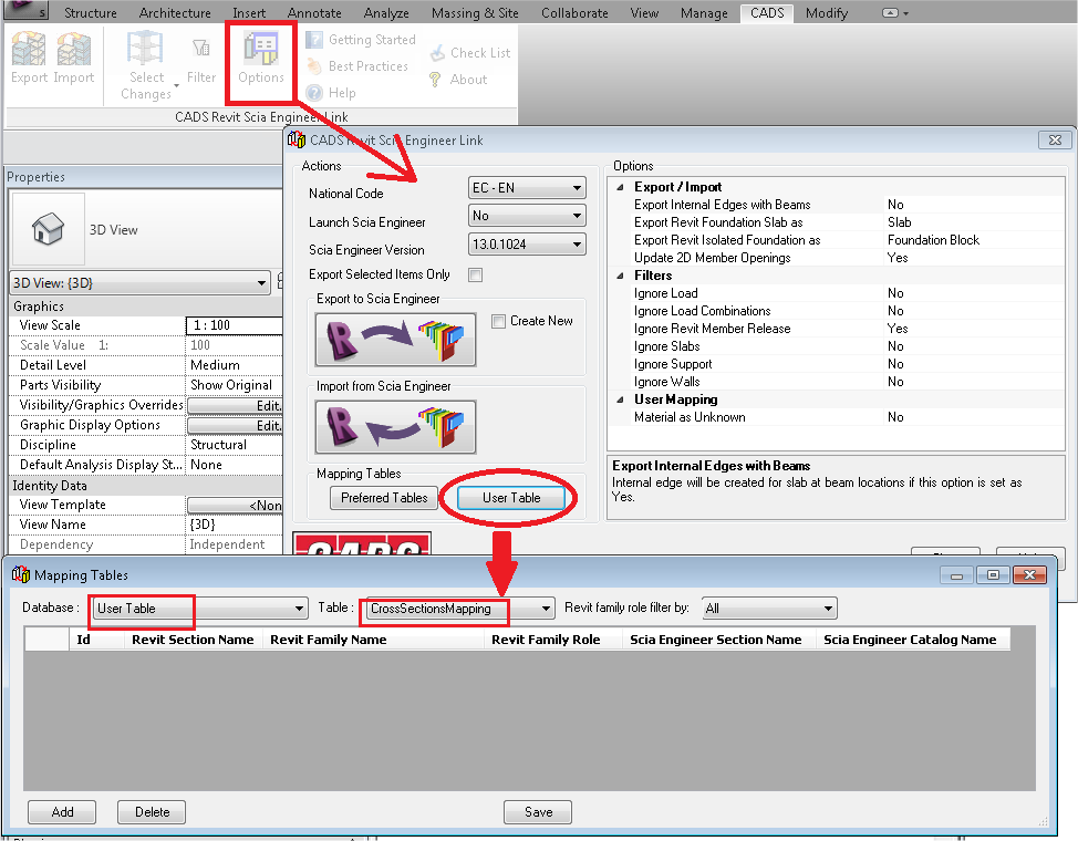
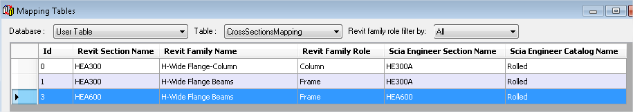
- To add the mapping for this section to the Revit link, first click ‘Close’. Go back to the options of the Revit link, and open the ‘User table’. The user table contains the mapping defined by the user. If you click on ‘User Table’ in the new window, you will see different mappings that are already inserted. Now we want to add mapping for the database ‘user table’ in the table ‘CrossSectionsMapping’.
- So choose ‘Add’.
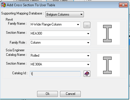
In the window ‘Add Cross Section To User Table’, follow the next steps:- 1. Supporting Mapping Database: choose ‘Belgium Columns’ (or ‘Europe Specific Sections’ or ‘Netherland Columns’)
- 2. Family Role = Column
- 3. Family Name = H-Wide Flange-Column
- 4. Section Name = HEA300 (you can start typing, instead of scrolling)
- Then for the options under ‘SCIA Engineer’, Catalog Name = Rolled, and search the section HE300A. You should have the following options:
- Afterwards, click on ‘OK’.
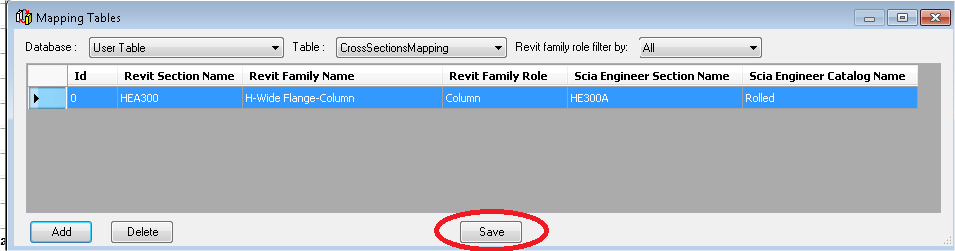
You will see that there is a new line in the mapping table. Now click on ‘Save’ to keep this new mapping. This will now always be used if you use the Revit Link.
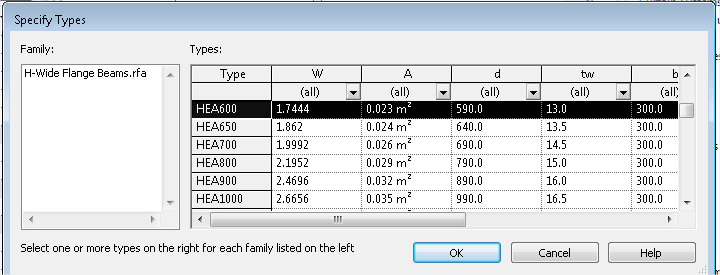
- Now we will add the same cross section, but then for the frames, and also the HEA600 from SCIA Engineer. If you do not know the name in SCIA Engineer, then run the Revit link again, and look at the message indicated in red. For the HEA600, it will be necessary to use the ‘Netherlands Beams’ (for example).
- After you have clicked on save, close the mapping table with the cross in the corner. Try to use the Revit link again.
It is possible that you have mapped everything correctly in the mapping table, but it is still possible that the ‘Revit Section Name’ you refer to, is from a family which has not been loaded.
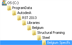
To solve this, go to ‘Insert -> Load from Library’.
The family library for Revit Structure is by default in the ProgramData folder.
(all families are not loaded by default, because it would make the software much slower)
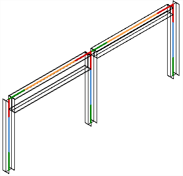
- If the import went successfully, you will see the same structure as you had in SCIA Engineer:
The Revit link is mainly developed for exporting the data from Revit structure to SCIA Engineer.
Most changes made in SCIA Engineer can be imported back to Revit Structure.
But the functionality has its limitations. If you wish to check the possibilities (and impossibilities of the link, we refer to the help of the Revit Plugin. We refer to the plug-in instead of placing the information here, because a newer version of the plug-in will allow more, and these options will also be updated in its help file.
In the next image you can see that the help file has been used to check the possibilities concerning load combinations.
The Revit link was originally implemented to send files/models from Revit Structure to SCIA Engineer. It is also possible to send files back from SCIA Engineer to Revit Structure, but it can also still be possible to transfer these changes verbally to the architect using Revit Structure so that he is fully aware of the changes. But as you will see in examples 2 and 3, changed, added and deleted items can be perfectly exchanged from SCIA Engineer to Revit Structure
Modification of cross-section in SCIA Engineer
- Take the project which we ended with in example 1. We are now going to adapt the column cross-section in SCIA Engineer and import it back in the same existing Revit Structure project.
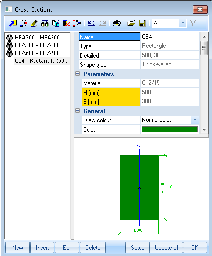
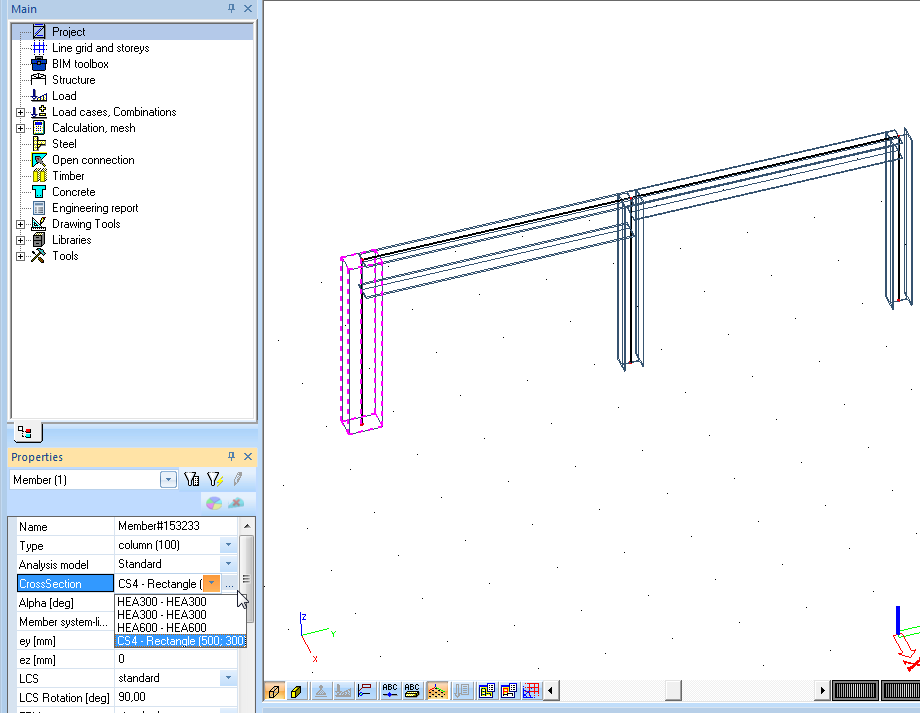
- In SCIA Engineer, we are going to add the default rectangular concrete cross-section and change the property of one column to this cross-section.
- As you can see, the new rectangular cross-section is applied to one of the columns. The next step is to export the SCIA Engineer project to an .r2s file, and to import this file into Revit Structure. Be sure to deselect everything in SCIA Engineer first, otherwise only the selection will be exported.
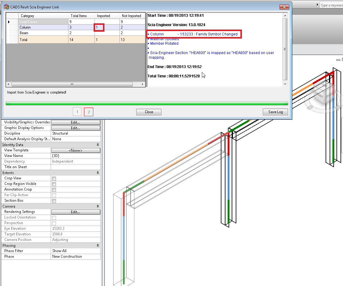
- As you can see, only the changed element will be imported. The log mentions that the family symbol has changed. Only the imported elements cause changes in the model, so the imported column is the on we changed, and the message refers to exactly that column.
Adding elements in SCIA Engineer
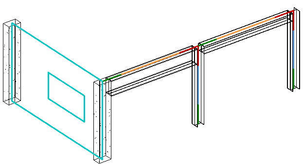
- For this example, we will continue with the modified SCIA Engineer project from the end of example 2. We are going to add a column and a wall and import the entire project in Revit Structure.
- In the image below, the concrete column has been copied, and a (steel) wall has been placed between the two concrete columns. An opening has also been added to the wall (it is important that vertical 2D elements have the type ‘wall’ and horizontal the type ‘plate’).
- Next step is importing the project in to the Revit project which we acquired at the end of example 2. The import log will look like this:
- The new elements are the one imported, the already existent (and not changed) have not been imported again. One column and one wall were imported. Also the opening has been imported (this opening could also be imported later on).
Open topic with navigation