![]()
|
||
|
|
||
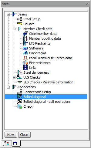
Autodesign of bolted diagonal is the same part as the Autodesign located in the standard Steel > Connections > Bolted diagonal.
When the user clicks on action button Autodesign then the following dialogue appears. The dialogue is a bit different than the one used in the general Autodesign dialogue but the functionality is the same.
We will focus on Autodesign running from Autodesign service in this case. Generally, results based on the same settings in Autodesign and in the individual service have to be the same.
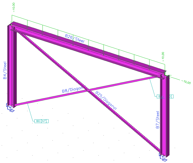
Let us consider a very simple example of a steel frame with bolted diagonals for Autodesign. The structure is subject to the uniform load and to the axial force at the end. The aim of this example is to find the optimal dimensions of the bolted diagonal connection.
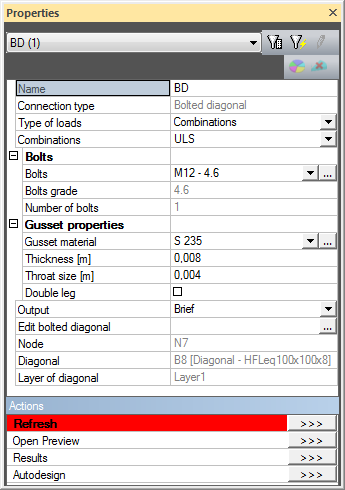
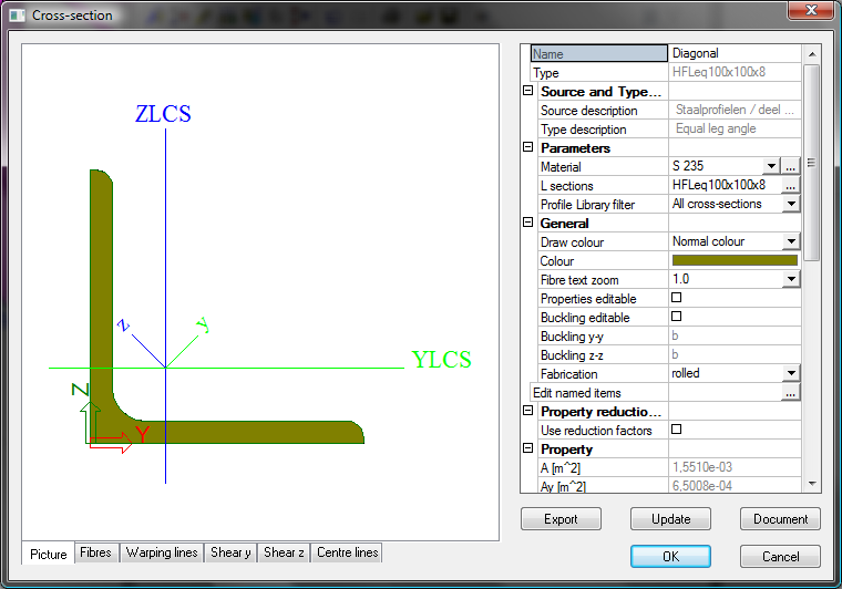
Bolt diagonal has the following cross-section. The parameters of bolted connection are shown in the following figure.
The Autodesign function is defined for this cross-section. You can see the settings on the following figure.
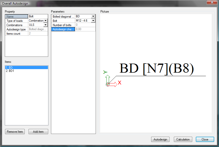
The settings are shown in the figure above.
Bolted diagonal
Specifies the bolted diagonal to be optimised.
Bolt
Specifies the bolt used.
Optimised check (informative)
Shows the unity check for the optimised connection.
Autodesign can be run in one step using Autodesign all.
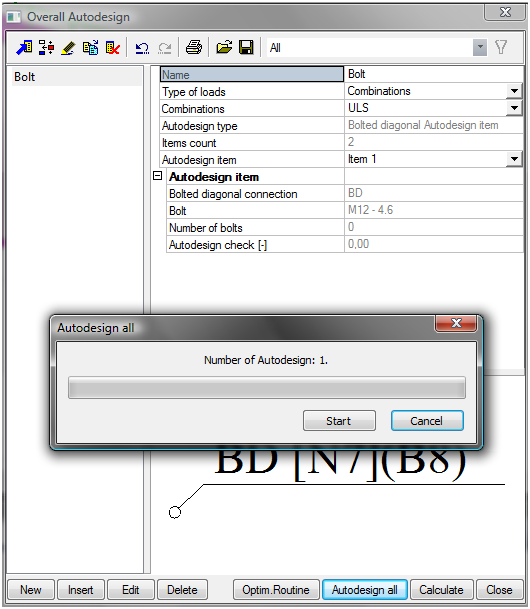
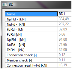
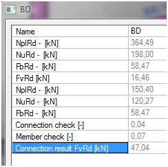
The results are automatically printed in preview. One bolt for each connection is enough. Instead of originally designed four bolts.
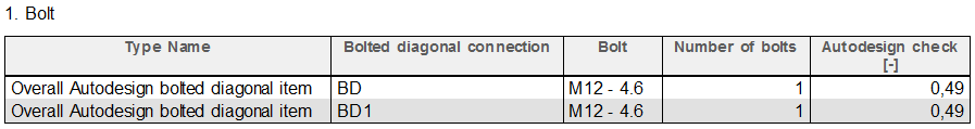
The comparison of initial and optimized values of bolted connections is clear from the following table.
|
Initial |
Optimized |
|
|
|