Open topic with navigation

Command properties
Command properties
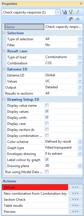
Concrete checks run from the new commands mentioned in chapter "Concrete in SCIA Engineer". The command for these checks includes standard items where it is possible to select member, type of load, filter, extreme and others. The description of all values is the following.
Name
User is allowed to name the Check. It might be very useful for better specification and orientation, especially in engineering report. Default name is always name of the command in the tree.
Selection
This attribute influences the total amount of members, which will be taken into the concrete checks. There are four possibilities to be chosen from:
- All – all active 1D members will be checked
- Current – only selected 1D members will be checked
- Advanced – user may define the selection more specifically with relation to previous selection
- Named selection – only 1D members from certain named selection, will be checked. new attribute “Named selection” will appear in the properties
- Design groups - groups of members with same length, type, cross-section or additional rules, see "Design groups"
Type of loads
By this attribute user defines the type of the load for checks. There are three possibilities to choose from:
- Combinations – user may choose from all combinations
- Load cases – user may choose from all load cases
- Class – user may choose from all result classes
In dependence on selected type of the load, new attribute Combination or Load cases or Class will appear right under this attribute. User may select desired Combination, Load case or Class from filtered list here.
Filter
It is possible to define filter for adjusting already selected type of selection. This will affect the number of 1D member taken into the check. User may select one from the following possibilities:
- No – no filter will be applied
- Wildcard – user may define the attributes for selection by himself
- Material – user may select specific material
- Cross-section – user may select specific cross-section
- Layer – user may select desired layer
- Type of beam
Again, after selection one possibility a new appropriate attribute will be displayed right under, for further selection.
Extreme
This attribute defines which results should be shown in Preview window or document. User may choose from five possibilities:
- Section - Results will be presented in all sections on all member - WARNING: displaying standard or detailed results with these extreme selected can take a lot of time
- Cross-section - Extremes on all types of sections will be displayed
- Design group - Extremes on design groups will be displayed
- Member - Extremes per members will be displayed
- Global - Only global extremes will be displayed
Values
Each design or check includes its own values. Usually Unity check is the first typical value for all checks. There is also possibility to see More component.
Output
This attribute defines type of numerical output. There are available three levels of numerical outputs:
- Brief – one table for all checks with the unity checks, default Engineering Report table.
- Standard – more detailed output coming from SCIA Design Forms
- Detailed – very deep output coming from SCIA Design Forms
Results in sections
This setting specify on which sections will be calculation performed and extremes will be found
- All - All sections are evaluated
- Selected - Only selected sections are evaluated. Sections are defined in service Structure
Drawing setup
By selecting edit button for this parameter, a 1D results display dialogue will be open. Here user may specify the representation of check results on 1D member. This dialogue is a standard dialogue for graphical presentation of results on 1D member. The most important settings are the following:
- Limits – maximal and minimal values which should be drawn
- Description – which information is required to be printed (values, section, load case or combination and units)
- Angle of text – angle of text related to centreline of the member
- Setup for more components
- same scale or height
- spaces between diagrams and shifting of the first diagram
Run using Model Data files (Debug)
This check box allows to save all model data including detailed trace of all calculation steps into files in SCIA Engineer TEMP folder.
Action buttons
There are two buttons in the lower part of the Properties dialogue.
- Refresh – this button starts the process of check itself and it is needed to press this button to refresh previous checked results and to get new results, based on chosen attributes)
- Preview – this button opens Preview window with tables containing results of finished check
Note: Content of command properties can be slightly different in future versions
Open topic with navigation