![]()
|
||
|
|
||
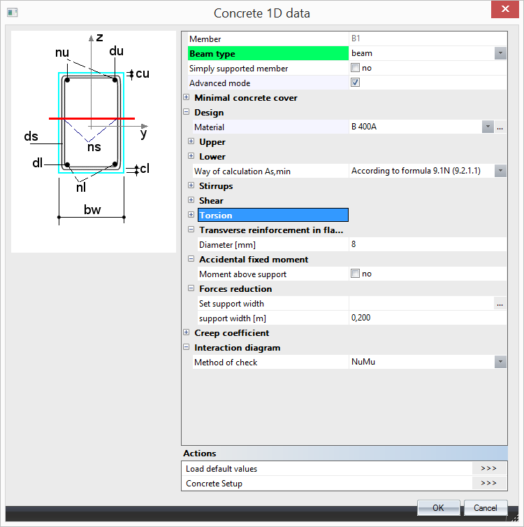
These settings overwrite the global settings for a specific member. Member data can easily be copy-pasted to similar members. There is differentiation based on type of member (beam, column, beam slab, rib). As in the case of setup, Member data has been also restyled. Local settings contains a contain about the same input parameters and calculation settings as the global settings in setup. Moreover, user can set his/her own value of limit deflection and limit width of crack, define more environmental classes than just one as in previous version.
|
|
| Concrete Advanced member data | Concrete member data |
1D Member data are arranged similarly as Concrete settings (structure). Generally, there are the following items.
| Description |
Type of calculation creep coefficient: - user value - creep coefficient inputted directly by the user - auto - creep coefficient is calculated automatically by the program |
| Default | Combo box ; Typeϕ = Auto / User input; default = Auto |
|
Code |
Annex B.1 |
| Level | Standard |
|
Member |
1D member (Beam / Column / Beam Slab / Rib) |
| Description | Relative humidity of ambient environment |
| Default | Edit box; RH = 50 % |
|
Code |
Annex B.1 |
| Level | Advanced |
|
Figure |
1D member (Beam / Column / Beam Slab / Rib) |
| Description | Age of concrete at loading of the member |
| Default | Edit box; t0 = 28 days |
|
Code |
Annex B.1 |
| Level | Advanced |
|
Member |
1D member (Beam / Column / Beam Slab / Rib) |
| Description | Age of concrete at the moment considered. It means, time, which creep coefficient is calculated for. |
| Default | Edit box; t = 1825 days |
|
Code |
Annex B.1 |
| Level | Advanced |
|
Member |
1D member (Beam / Column / Beam Slab / Rib) |
| Description | Possibility to use effective E modulus of concrete. It means the long-term behaviour of concrete is covered in the analysis of the crack width, stress limitations and stiffness calculation. |
| Default | Check box, default NO |
|
Code |
7.1(2) |
| Level | Advanced |
|
Member |
1D member (Beam / Column / Beam Slab / Rib) |
| Description |
The geometric imperfection is calculated as for isolated member, if this parameter is ON |
| Default | Check box; default True |
|
Code |
5.8.8.2 |
| Level | Advanced |
|
Member |
Column |
| Description |
Determination of the direction for calculation of second order effect and geometrical imperfection effect and geometrical imperfection according to conditions 5.38a a 5.38b - Auto: automatic calculation of direction for taking into account second order effect and geometrical imperfection according to conditions 5.38a a 5.38b - Uniaxial: second order effect and geometrical imperfection is taken into account only in one (more unfavourable direction) - Biaxial: second order effect and geometrical imperfection is taken into always in both directions |
| Default | Combo box Auto / uniaxial / biaxial; default Auto |
|
Code |
5.8.9 |
| Level | Advanced |
|
Member |
Column |
| Description |
The minimum value of eccentricity is taken into account for calculation first order eccentricity, if this parameter is ON. |
| Default | Check box default True |
|
Code |
6.1.4 |
| Level | Advanced |
|
Member |
Column |
| Description |
The geometric imperfection is taken into account for calculation first order eccentricity, if this parameter is ON. |
| Default | Check box, default True |
|
Code |
5.2.5 |
| Level | Standard |
|
Member |
Column |
| Description |
The second order effect is taken into account, if slenderness is greater than limit slenderness and this parameter is ON. |
| Default | Check box, default True |
|
Code |
5.8.8 |
| Level | Standard |
| Member |
Column |
| Description |
Estimation ratio of longitudinal reinforcement for calculation mechanical reinforcement ratio in design of reinforcement. Mechanical ratio is calculated for calculation limit slenderness (chapter 5.8.3.1(1) and second order effect - method based on nominal curvature (formula 5.36) |
| Default | Edit box; default μs = 1 % |
|
Code |
6.2.3 |
| Level | Advanced |
|
Member |
Column |
| Description |
If the check box is ON , the additional tensile force caused by shear force is taken into account by using shift rules |
| Default | Check box default True |
|
Code |
9.2.1.3(2) |
| Level | Standard |
|
Member |
Beam / Beam Slab / Rib |
| Description |
Method for design of longitudinal reinforcement for beams and beams slab |
| Default | Combo box; Auto / Uniaxial around y / Uniaxial around z / Biaxial; Default Auto |
|
Code |
- |
| Level | Advanced |
|
Member |
Beam / Beam Slab / Rib |
| Description |
Method for design of longitudinal reinforcement for columns |
| Default | Combo box; Auto / Uniaxial around y / Uniaxial around z / Biaxial; Default Auto |
|
Code |
- |
| Level | Advanced |
|
Member |
Column |
| Description |
Possibility to set method for evaluation of results using interaction diagram: - NRd - assuming MEd is constant - MRd - assuming NEd is constant - NRdMrd - - assuming eccentricity is constant - Mrdy - assuming MEdz is constant - Mrdz - - assuming MEdy is constant |
| Default | Combo box NRd / MRd / NRdMrd / Mrdy / Mrdz, default NRdMRd |
|
Code |
6.1 |
| Level | Standard |
|
Member |
1D member (Beam / Column / Beam Slab / Rib) |
| Description |
Type calculation of angle of between of compression strut and member axis for shear check - Auto: automatic calculation of minimum angle based on condition VEd≤ VRd.max - User(angle) : the value is inputted by the user as angle - User(cotangent) : the value is inputted by the user as cotangent of the value |
| Default | Combo box, Auto / User (angle) / User (cotangent); default User (angle) |
|
Code |
6.2.3 |
| Level | Standard |
|
Member |
1D member (Beam / Column / Beam Slab / Rib) |
| Description |
Input type for angle between compression strut and member axis for longitudinal shear check - User(angle): the value is inputted by the user as angle - User(cotangent): the value is inputted by the user as cotangent of the value |
| Default | Combo box, User (angle) / User (cotangent); default User (angle) |
|
Code |
6.2.4(4) |
| Level | Advanced |
|
Member |
Beam / Beam Slab |
| Description |
Angle between compression strut and member axis for longitudinal shear check; editable only if type of calculation of compression strut angle is User (angle) |
| Default | Edit box, ϕf = 40 ° |
|
Code |
6.2.4(4) |
| Level | Advanced |
|
Member |
Beam / Beam Slab / Rib |
| Description |
Cotangent of the angle between compression strut and member axis for longitudinal shear check; editable only if type of calculation of compression strut angle is User (cotangent) |
| Default | Edit box, cot ϕf =1,2 |
|
Code |
6.2.4(4) |
| Level | Advanced |
|
Member |
Beam / Beam Slab / Rib |
| Description |
Type of equivalent thin-walled cross-section used for calculation of cross-section capacity in torsion |
| Default | Combo box; Automatic / From stirrups from torsion / From effective CSS / From effective rectangular CSS; / User input of thin-walled closed cross-section; default Automatic |
|
Code |
6.3.1(3) |
| Level | Advanced |
|
Member |
1D member (Beam / Column / Beam Slab / Rib) |
| Description |
An area of thin walled closed cross-section enclosed by the centre-lines of the connecting walls, including inner hollow areas; visible only if Equivalent thin walled cross-section is set to User input of thin-walled closed cross-section |
| Default | Edit box; default 0 mm2 |
|
Code |
6.3.1(3) |
| Level | Advanced |
|
Member |
1D member (Beam / Column / Beam Slab / Rib) |
| Description |
Outer circumference of the cross-section; visible only if Equivalent thin walled cross-section is set to User input of thin-walled closed cross-section |
| Default | Edit box; default 0 mm2 |
|
Code |
6.3.1(3) |
| Level | Advanced |
|
Member |
1D member (Beam / Column / Beam Slab / Rib) |
| Description |
Thickness of equivalent thin-walled cross-section. It may be taken as A/u, but should not be taken as less than twice the distance between edge and centre of the longitudinal reinforcement; visible only if Equivalent thin walled cross-section is set to User input of thin-walled closed cross-section |
| Default | Edit box; default 0 mm2 |
|
Code |
6.3.1(3) |
| Level | Advanced |
|
Member |
1D member (Beam / Column / Beam Slab) |
| Description |
Type of tensile strength of concrete used for calculation of cracking forces in SLS checks (stresses and deflections). It is possible to select between fctm (Table 3.1) and fctm,fl (Clause 3.1.8). |
| Default | Combo box fctm / fctm,fl (default fctm) |
|
Code |
7.1(2) |
| Level | Advanced |
|
Member |
1D member (Beam / Column / Beam Slab / Rib) |
| Description |
Value of strength of concrete used for calculation of cracking forces in SLS checks (stresses and deflections). It is possible to select between a) 0 MPa - first crack appears when tensile stress is reached in concrete cross-section b) fcteff - first crack is appears when effective tensile strength is reached in cross-section |
| Default | Combo box 0 MPa/ fctm,eff (default fct,eff) |
|
Code |
7.1(2) |
| Level | Advanced |
|
Member |
1D member (Beam / Column / Beam Slab / Rib) |
| Description |
User defined crack width |
| Default | Edit box; winp = 0,3 mm |
|
Code |
7.3.1(5) |
| Level | Standard |
|
Member |
1D member (Beam / Column / Beam Slab / Rib) |
| Description |
Maximal additional (total - immediate) displacement allowed for 1D member expressed as span / depth ratio |
| Default | Edit box; xadd = 500 |
|
Code |
7.4.1(5) |
| Level | Standard |
|
Member |
1D member (Beam / Column / Beam Slab / Rib) |
| Description |
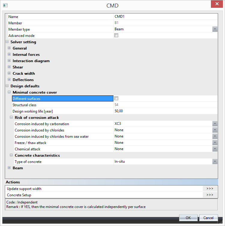
If YES, then the minimal concrete cover is calculated independently per surface and all items for concrete cover are split into lower and upper |
| Default | Edit box , default = 50 years |
|
Code |
- |
| Level | Standard |
|
Figure |
- |
| Member | Beam / Beam Slab / Rib |
| Description |
Design working life is information used for determination of minimal concrete cover |
| Default | Edit box , default = 50 years |
|
Code |
4.4.1.2(5), table 4.3N |
| Level | Standard |
|
Figure |
- |
| Member | 1D member (Beam / Column / Beam Slab / Rib) |
| Description |
Exposure class caused by carbonation is used for determination of minimal concrete cover in Table 4.4N |
| Default | Combo box; None / X0 /XC1 / XC2 / XC3 / XC4; default =XC3 |
|
Code |
4.4.1.2(5), table 4.3N |
| Level | Standard |
|
Figure |
- |
| Member | 1D member (Beam / Column / Beam Slab / Rib) |
| Description |
Exposure class caused by chlorides is used for determination of minimal concrete cover in Table 4.4N |
| Default | Combo box; None / XD1 / XD2 / XD3; default =None |
|
Code |
4.4.1.2(5), table 4.3N |
| Level | Standard |
|
Figure |
- |
| Member | 1D member (Beam / Column / Beam Slab / Rib) |
| Description |
Exposure class caused by chlorides from sea water is used for determination of minimal concrete cover in Table 4.4N |
| Default | Combo box; None / XS1 / XS2 / XS3; default =None |
|
Code |
4.4.1.2(5), table 4.3N |
| Level | Standard |
|
Figure |
- |
| Member | 1D member (Beam / Column / Beam Slab / Rib) |
| Description |
Additional Exposure class caused by freezing or thawing |
| Default | Combo box; None / XF1 / XF2 / XF3; default = None |
|
Code |
4.4.1.2(12) |
| Level | Standard |
|
Figure |
- |
| Member | 1D member (Beam / Column / Beam Slab / Rib) |
| Description |
Additional Exposure class caused by chemical attack |
| Default | Combo box; None / XA1 / XA2 / XA3; default = None |
|
Code |
4.4.1.2(12) |
| Level | Standard |
|
Figure |
- |
| Member | 1D member (Beam / Column / Beam Slab / Rib) |
| Description |
Additional Exposure class caused by abrasion attack |
| Default | Combo box; None / XM1 / XM2 / XM3; default = None |
|
Code |
4.4.1.2(13) |
| Level | Advanced |
|
Figure |
- |
| Member | 1D member (Beam / Column / Beam Slab / Rib) |
| Description |
To take into account additional deviation to nominal concrete cover caused by special geometric control |
| Default | Check box; default = True |
|
Code |
4.4.1.3(3) |
| Level | Advanced |
|
Figure |
- |
| Member | 1D member (Beam / Column / Beam Slab / Rib) |
| Description |
To take into account additional deviation to nominal concrete cover caused by special concrete quality control |
| Default | Check box; default = True |
|
Code |
4.4.1.2(5) |
| Level | Advanced |
|
Figure |
- |
| Member | 1D member (Beam / Column / Beam Slab / Rib) |
| Description |
To take into account additional deviation to nominal concrete cover caused by casting on atypical surface |
| Default | Combo box; Standard / Against prepared ground / Again soil / Uneven surface default = Standard |
|
Code |
4.4.1.3(4) |
| Level | Advanced |
|
Figure |
- |
| Member | 1D member (Beam / Column / Beam Slab / Rib) |
| Description |
To take into account additional deviation to nominal concrete cover caused by production type |
| Default | Combo box; In-situ / Prefabricated ; default = In-situ |
|
Code |
4.4.1.3(1P, 3) |
| Level | Advanced |
|
Figure |
- |
| Member | 1D member (Beam / Column / Beam Slab / Rib) |
| Description | |
| Default | Link to library; default taken from setting in Project data |
|
Code |
- |
| Level | Standard |
|
Figure |
- |
| Member | Beam / Rib |
| Description |
Information about diameter of upper of reinforcement |
| Default | Edit box; default ds,u = 16 mm |
|
Code |
- |
| Level | Standard |
|
Figure |
- |
| Member | Beam / Rib |
| Description |
Information about type of cover of upper reinforcement |
| Default | Combo box; Auto / User; default = Auto |
|
Code |
4.4.1 |
| Level | Standard |
|
Figure |
- |
| Member | Beam / Rib |
| Description |
Possibility to define concrete cover of upper reinforcement; this item is visible only if the item above is set to User |
| Default | Edit box; cu = 30 mm |
|
Code |
4.4.1 |
| Level | Standard |
|
Figure |
- |
| Member | Beam / Rib |
| Description |
Information about diameter of lower of reinforcement |
| Default | Edit box; default ds,l = 16 mm |
|
Code |
- |
| Level | Standard |
|
Figure |
- |
| Member | Beam / Rib |
| Description |
Information about type of cover of lower reinforcement |
| Default | Combo box; Auto / User; default = Auto |
|
Code |
4.4.1 |
| Level | Standard |
|
Figure |
- |
| Member | Beam / Rib |
| Description |
Possibility to define concrete cover of lower reinforcement; this item is visible only if the item above is set to User |
| Default | Edit box; cl = 30 mm |
|
Code |
4.4.1 |
| Level | Standard |
|
Figure |
- |
| Member | Beam / Rib |
| Description |
Information about type of cover of side reinforcement |
| Default | Combo box; Auto / User; default = Auto |
|
Code |
4.4.1 |
| Level | Standard |
|
Figure |
- |
| Member | Beam / Rib |
| Description |
Possibility to define concrete cover of side reinforcement; this item is visible only if the item above is set to User |
| Default | Edit box; cs = 30 mm |
|
Code |
4.4.1 |
| Level | Standard |
|
Figure |
- |
| Member | Beam / Rib |
| Description |
Information about material of stirrups reinforcement |
| Default | Link to library; default taken from setting in Project data |
|
Code |
- |
| Level | Standard |
|
Figure |
- |
| Member | Beam / Rib |
| Description |
Information about diameter of stirrups |
| Default | Edit box; dss = 8 mm |
|
Code |
- |
| Level | Standard |
|
Figure |
- |
| Member | Beam / Rib |
| Description |
Information about number of cuts for shear reinforcement |
| Default | Edit box; ns = 2 |
|
Code |
- |
| Level | Standard |
|
Figure |
- |
| Member | Beam / Rib |
| Description |
Angle between shear reinforcement and the beam axis perpendicular to the shear force |
| Default | Edit box; α = 90 ° |
|
Code |
- |
| Level | Standard |
|
Figure |
- |
| Member | Beam / Rib |
| Description |
Information about material of longitudinal reinforcement |
| Default | Link to library; default taken from setting in Project data |
|
Code |
- |
| Level | Standard |
|
Figure |
- |
| Member | Beam slab |
| Description |
Information about diameter of upper of reinforcement |
| Default | Edit box; default ds,u = 16 mm |
|
Code |
- |
| Level | Standard |
|
Figure |
- |
| Member | Beam slab |
| Description |
Information about type of cover of upper reinforcement |
| Default | Combo box; Auto / User; default = Auto |
|
Code |
4.4.1 |
| Level | Standard |
|
Figure |
- |
| Member | Beam slab |
| Description |
Possibility to define concrete cover of upper reinforcement; this item is visible only if the item above is set to User |
| Default | Edit box; cu = 30 mm |
|
Code |
4.4.1 |
| Level | Standard |
|
Figure |
- |
| Member | Beam slab |
| Description |
Information about diameter of lower of reinforcement |
| Default | Edit box; default ds,l = 16 mm |
|
Code |
- |
| Level | Standard |
|
Figure |
- |
| Member | Beam slab |
| Description |
Information about type of cover of lower reinforcement |
| Default | Combo box; Auto / User; default = Auto |
|
Code |
4.4.1 |
| Level | Standard |
|
Figure |
- |
| Member | Beam slab |
| Description |
Possibility to define concrete cover of lower reinforcement; this item is visible only if the item above is set to User |
| Default | Edit box; cl = 30 mm |
|
Code |
4.4.1 |
| Level | Standard |
|
Figure |
- |
| Member | Beam slab |
| Description |
Information about material of main reinforcement |
| Default | Link to library; default taken from setting in Project data |
|
Code |
- |
| Level | Standard |
|
Figure |
- |
| Member | Column |
| Description |
Information about diameter of main of reinforcement |
| Default | Edit box; default ds,m = 16 mm |
|
Code |
- |
| Level | Standard |
|
Figure |
|
| Member | Column |
| Description |
Information about type of cover of main reinforcement |
| Default | Combo box; Auto / User; default = Auto |
|
Code |
4.4.1 |
| Level | Standard |
|
Figure |
- |
| Member | Column |
| Description |
Possibility to define concrete cover of main reinforcement; this item is visible only if the item above is set to User |
| Default | Edit box; cm = 30 mm |
|
Code |
4.4.1 |
| Level | Standard |
|
Figure |
- |
| Member | Column |
| Description |
Information about material of stirrups reinforcement |
| Default | Link to library; default taken from setting in Project data |
|
Code |
- |
| Level | Standard |
|
Figure |
- |
| Member | Beam / Column |
| Description |
Information about diameter of stirrups |
| Default | Edit box; dss = 8 mm |
|
Code |
- |
| Level | Standard |
|
Figure |
- |
| Member | Beam / Column |
| Description |
Information about number of cuts for shear reinforcement |
| Default | Edit box; ns = 2 |
|
Code |
- |
| Level | Standard |
|
Figure |
- |
| Member | Beam / Column / Rib |
| Description |
Angle between shear reinforcement and the beam axis perpendicular to the shear force |
| Default | Edit box; α = 90 ° |
|
Code |
- |
| Level | Standard |
|
Figure |
- |
| Member | Beam / Column / Rib |
This group of items is related to user defined shear reinforcement which is considered as real inputted reinforcement on member. This replaces user defined shear reinforcement which is not taken into account for design. Check shear and torsion is not influenced by this settings.
| Description |
Information about material of inputted stirrups reinforcement |
| Default | Link to library; default taken from setting in Project data |
|
Code |
- |
| Level | Advanced |
|
Figure |
- |
| Member | Beam / Column / Rib |
| Description |
Angle between shear reinforcement and the beam axis perpendicular to the shear force |
| Default | Edit box; α = 90 ° |
|
Code |
- |
| Level | Advanced |
|
Figure |
- |
| Member | Beam / Column / Rib |
| Description |
Information about defined shear reinforcement taken into account as real reinforcement for shear design |
| Default | 0 mm2 |
|
Code |
- |
| Level | Advanced |
|
Figure |
- |
| Member | Beam / Column / Rib |