![]()
|
||
|
|
||
There is available new functionality for 2D members combining design of reinforcement for ULS and SLS from version SCIA Engineer 19.1. The SLS part consists of design based on the followings:
The procedure can be described in the following steps:
comparison calculated crack width (wk) with maximal crack width (wk,max) for required ULS reinforcement
If wk<=wk,max then everything is fine and no other steps are needed, it means As,ult is optimal also from the point of As,serv ; As,serv= As,ult;
If wk>wk,max then optimization routine must be run.
The area of tensile reinforcement in effective zone only (Act,eff) must be increased by servcoeff which will be calculated as follows:
In case of crack width only:
servcoeff=wk,coeff= (wk / wk,max ) 0,5+0,01
In case of reinforcement stress only:
servcoeff=ss,coeff= (ss / ss,lim )+0,005
servcoeff = max(ss,coeff;wk,coeff)
Maximal number of iterations for one mesh element and direction is 10. If then number of iterations is exceeded we will stop with warnings.
The optimization stops when unity check of crack width is between 90-100%.
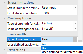
Maximal crack width can be determined automatically based on NA or can be defined manually via Concrete settings or 2D concrete member data.
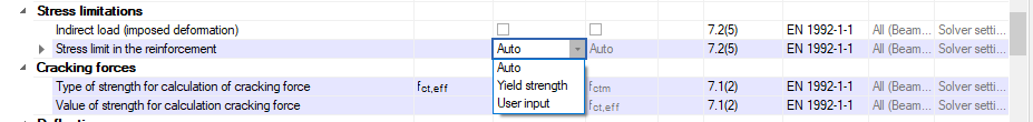
Maximal stress in reinforcement can be determined automatically based on NA or can be defined manually via Concrete settings or 2D concrete member data.
When the statically reinforcement is designed based on ULS +SLS then verification of detailing provisions must be done. The same procedure and warnings as used for ULS design will be applied for ULS+SLS design, juts move one step further.
Then the final As,req for direction (1,2) and surface (+,-) is the following and must respect minimal and maximal areas from detailing provisions:
As,req,1,2,± = min (max(As,ult,1,2,±; As,serv,1,2,±; As,min); As,max)
where:
Value wk is calculated for internal forces corresponding to each surface and each direction. This leads to maximally 4 calculation of wk. This can be limited to 2 runs only, in case of the same direction of reinforcement in lower and upper surface.
Designed areas for SLS (As,servare calculated in directions of principal stresses. It means these areas must be recalculated back to directions of reinforcement.
All chapters including changes coming from national annexes for particular country.