![]()
|
||
|
|
||
Project file: Benchmark_(EC_EN_1993)_43.esa
SCIA Engineer Version R18.1
In this benchmark the uplift purlin design according to EN 1993-1-3 chapter 10 is evaluated.
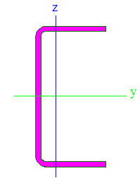
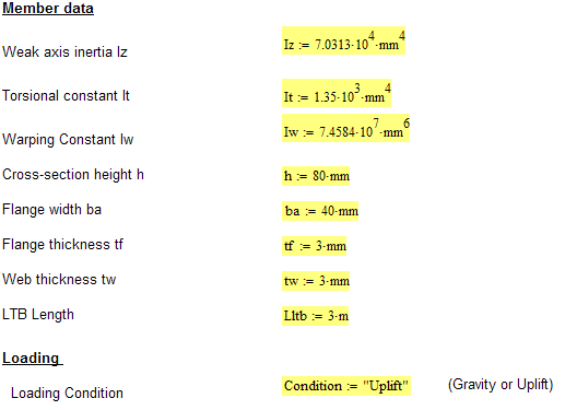
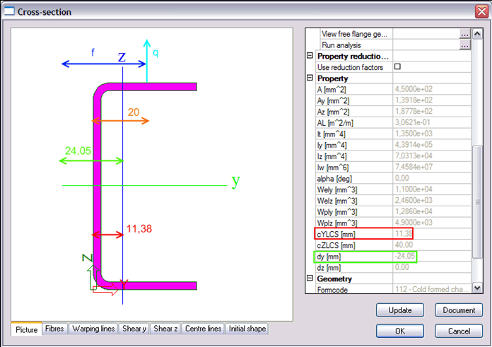
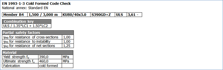
The member has a KU80/40x3.0 cross-section, a length of 3m and is fabricated of S390GD+Z material.
At the top flange the member is connected to a diaphragm of type E96/1.50. The bolts are positioned in the bottom flange of the diaphragm and each rib is connected. The extremities of the purlin are simply supported.
The purlin is loaded in uplift by two loads: a permanent point load of 5 kN in the middle of the member and a variable line load of 2 kN/m. Both loads are combined according to a ULS Set B combination.
Both the resistance of the cross-section according to article 10.1.4.1 as well as the buckling resistance of the free flange according to 10.1.4.2 are checked.
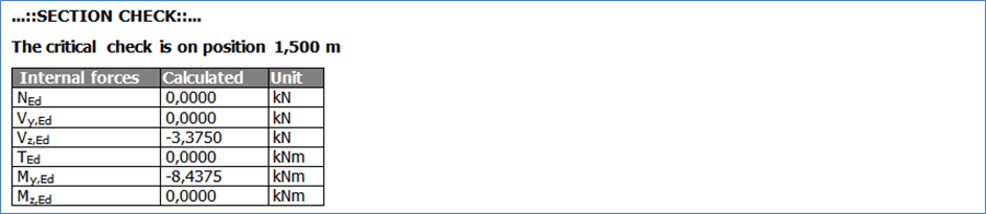
The results are verified by a manual calculation in the middle of the member, at 1,5m. Due to the fact that a point load is applied at this position, also the resistance to local transverse forces is evaluated.
The results are checked by a manual calculation.
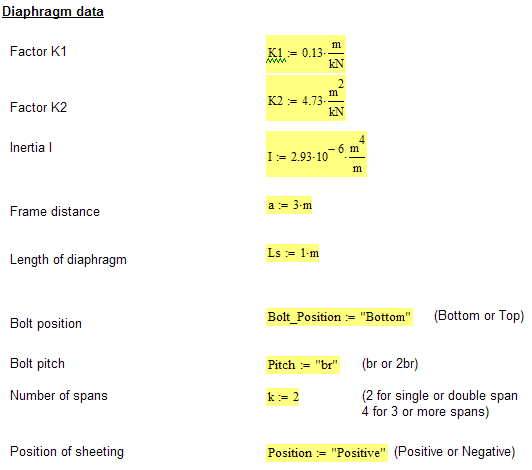
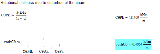
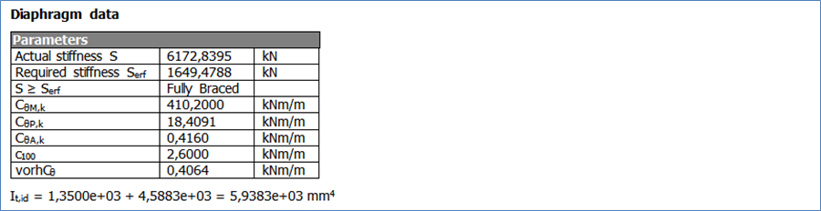
In a first step the shear stiffness of the diaphragm is determined using MathCad and compared to the required stiffness as given in article 10.1.1(6). In the same calculation the rotational stiffness of the diaphragm is determined.
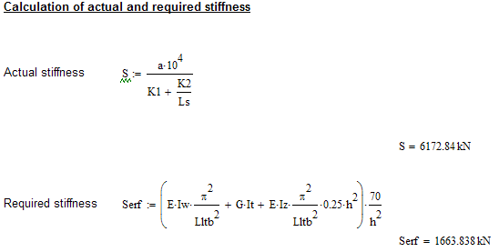
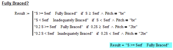
Since the shear stiffness is higher than the required stiffness the purlin may be considered as being laterally restrained in the plane of the sheeting and thus the provisions of chapter 10 may be applied.
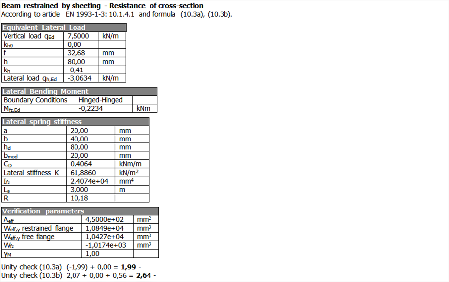
A) Cross-section Resistance of the free flange
Equivalent Lateral Load
The combination ULS returns in the mid section a bending moment of -8,44 kNm
=> qEd = 8 * M / L^2 = 8 * 8,44 / 3^2 = 7,5022222 kN/m (Printed positive due to uplift)
Since Iyz = 0 for this section this implies that kh0 = 0
The loading concerns Uplift loading. For Uplift the loading is assumed to act in the middle of the flange.
=> kh = kh0 - f / h with h = 80 mm and f = 24,05 - 11,38 + 20 = 32,67 mm
=> kh = 0 - 32,67 / 80 = -0,408375
The minus sign indicates that the loading is acting in the opposite sense as indicated in the code.
=> qh,Ed = -0,408375 * 7,5022222 kN/m = -3,06372 kN/m
The code indicates that the loading is acting from the web to the tip of the flange. However, due to the minus sign of kh the loading works in inverse direction, thus from the tip of the flange to the web (i.e. causing compression in the tip and tension in the web)
Free Flange Geometry
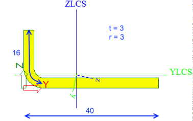
For a cold formed channel section the height of the free flange is taken as 1/5 h
=> 1/5 * 80 mm = 16 mm
This length is measured including the length of the rounding. The rounding has length (Pi/2) * (3 + 3/2) = 7,0686 mm
=> The length of the web part is: 16 - 7,0686 = 8,9314165294 mm
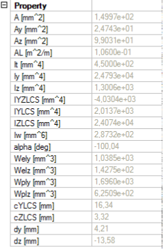
Af = 149,97 mm^2
Ifz = IZLCS = 24074 mm^4
Distance from centroid to web: 16,34 mm
=> Wfz,web = 24074 / 16,34 = 1473,32 mm^3
Distance from centroid to flange tip: 40 - 16,34 = 23,66 mm
=> Wfz,flange tip = 24074 / 23,66 = 1017,50 mm^3
Lateral Spring Stiffness
Since no anti-sag bars have been defined the length La = 3m
The connected flange with b = 40 mm
The fastener distance a = 0,5 b = 20 mm
Since this concerns a simple U-section the developed height of the web hd is taken as the full height h => hd = h = 80 mm
The determination of qh,Ed indicated that the loading is pointing from the tip to the web due to the minus sign of kh
Therefore, qh is bringing the purlin into contact with the sheeting at the purlin web
=> bmod = a = 20 mm
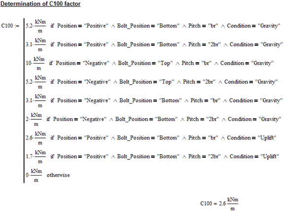
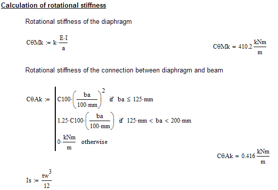
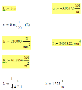
The rotational spring stiffness of the diaphragm is calculated as CD = cvorh = 0,4064 kNm/m (see MathCad calculation above).
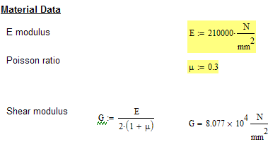
=> (1 / K ) = [[4 * (1 - 0,3 * 0,3) * 80 * 80 * (80 + 20)] / [210000 * 3 * 3 * 3] + [80 * 80] / [ 0,4064 * 1000] = 16,158896 mm^2/N
=> K = 0,061885 N/mm^2 = 61,8854 kN/m^2
=> R = [ 0,061885 * 3000^4 ] / [ pi^4 * 210000 * 24074 ] = 10,179
Lateral Bending Moment
Since it concerns a single span member the boundary conditions are taken as Hinged - Hinged.
Since the member is loaded by uplift the free flange is in compression.
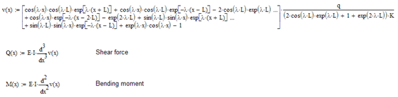
Using the analytical solution for Hinged-Hinged boundary conditions the Mfz,Ed value is determined in each section using MathCad:

Properties for the final check
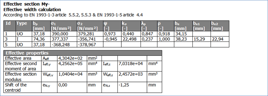
Since there is no axial force, Aeff is taken as Ag from the initial shape:
Aeff = 450,36 mm^2
The cross-section has a cZLCS coordinate of 40 mm. Using the Run Analysis tool, the effective shape for negative y-y bending is determined for a stress of 390 N/mm^2. This effective shape has an inertia Iy,eff = 4,2557 * 10^5 mm^4 and a cZLCS coordinate of 40,79 mm (Using iterations).
=> shift in neutral axis: 40,79 - 40 = 0,79 mm upward
Weff,restrained flange (top) = Iy,eff / (80 - 40,79) = 10853,61 mm^3
Weff, free flange (bottom) = Iy,eff / (40,79) = 10433,19 mm^3
Since Weff,y is different from Wel,y the safety factor Gamma M is taken as Gamma M1 = 1,00
Wfz = Wfz,flange tip = 1017,50 mm^3 since the lateral load causes compression in the flange tip.
Unity Check
| (10.3a) : | - [(8,44 * 10^6) / 10853,61] / [390 / 1,00] + [ 0 / 450,36] / [390 / 1,00 ] = - 1,99 + 0 = 1,99 (using absolute values) |
| (10.3b) : | [(8,44 * 10^6) / 10433,19] / [390 / 1,00] + [ 0 / 450,36] / [390 / 1,00 ] + [0,222 * 10^6 / 1017,50] / [390 / 1,00 ] = 2,07 + 0 + 0,56 = 2,64 |
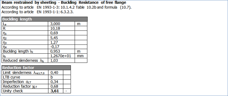
B) Buckling resistance of the free flange
Test to see if the free flange is in tension or compression: (tension is negative, compression is positive)
[(8,44 * 10^6) / 10433,19] + [ 0 / 450,36] = 809 => compression
=> The buckling resistance needs to be checked
Free Flange Buckling Length
La = 3000 mm
R = 10,179
Situation: Since the member has only one part for system length Ly it is seen as Simple span.
For uplift table 10.2b is used:
There are no anti-sag bars present on the member
Eta1 = 0.694
Eta2 = 5.45
Eta3 = 1.27
Eta4 = -0.168
=> lfz = 0.694 * 3000 * ( 1 + 5.45 * 10,179 ^1.27 ) ^ -0.168 = 952,933 mm
Reduction factor for flexural buckling of the free flange
ifz = sqrt ( Ifz / Af ) = sqrt (24074 / 149,97) = 12,67 mm
Lambda1 = pi * [210000 / 390] ^ 0,5 = 72,90
Lambda,fz = ( 952,933 / 12,67 ) / 72,90 = 1,0317
Lambda,0,LT = 0,4
LTB curve b => Alpha,LT = 0,34
Fi,LT = 0,5 * [ 1 + 0,34 * (1,0317 - 0,4 ) + 0,75 * 1,0317 * 1,0317 ] = 1,006552
Chi,LT = 1 / [ 1,006552 + sqrt ( 1,006552 * 1,006552 - 0,75 * 1,0317 * 1,0317) ] = 0,68025
Unity Check
| (10.7) : | (1 / 0,68025 ) * [ [(8,44 * 10^6) / 10433,19] / [390 / 1,00] + [ 0 / 450,36] / [390 / 1,00 ] ] + [0,222 * 10^6 / 1017,50] / [390 / 1,00 ] = 3,61 |
C) Resistance to Local Transverse Forces
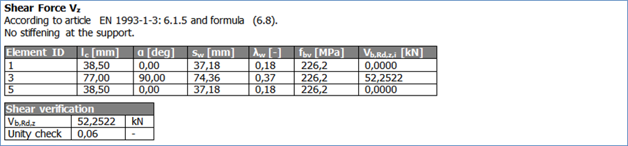
Resistance to local transverse force alone
The cross-section has a single unstiffened web. The resistance is determined according to article 6.1.7.2.
The transverse load of 6,75 kN is applied at 1,5m in the middle of the beam.
With a default bearing length Ss of 10 mm the distance of the edge of the load to a member end becomes c = 1500 – 10/2 = 1495 mm.
hw = 80 – 3/2 – 3/2 = 77 mm
=> c > 1,5 hw which implies the loading is categorized as Internal Loading.
=> With t = 3 mm Ss/t = 10 / 3 = 3,33 < 60 which implies (6.15d) needs to be used
k = 390 / 228 = 1,71
k3 = 0,7 + 0,3 * (90 / 90)^2 = 1,00
k4 = 1,22 – 0,22 * 1,71 = 0,84368
k5 = 1,06 – 0,06 * (3 / 3) = 1,00
Rw,Rd = = 1,00 * 0,84368 * 1,00 * [14,7 - (77 / 3) / 49,5 ] * [1 + 0,007 * 10 / 3] * 3 * 3 * 390 / 1,00 = 42,976 kN
Unity check: 6,75 / 42,976 = 0,16
Bending resistance
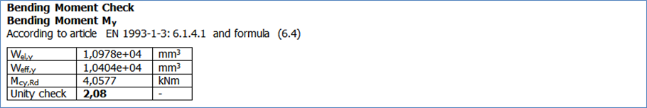
The section modulus of the gross section is Wel,y = 10978,33 mm^3
The effective section modulus under uplift loading is Weff,y = 10647,88 mm^3
Since the effective section modulus is smaller than the gropss section modulus the bending resistance is determined according to article 6.1.4.1 formula (6.4)
Mc,Rd = 10647,88 * 390 / 1,00 = 4,1527 kNm
With MEd = 8,44 kNm this gives:
Unity check: 8,44 / 4,1527 = 2,03
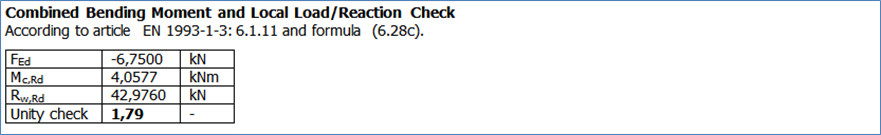
Combined bending and local transverse force
MEd = 8,44 kNm
Mc,Rd = 4,1527 kNm
FEd = 6,75 kN
Rw,Rd = 42,976 kN
Unity Check: [ (8,44 / 4,1527) + (6,75 / 42,976) ] / 1,25 = 1,75
The results correspond to the benchmark results.