Open topic with navigation

Camber
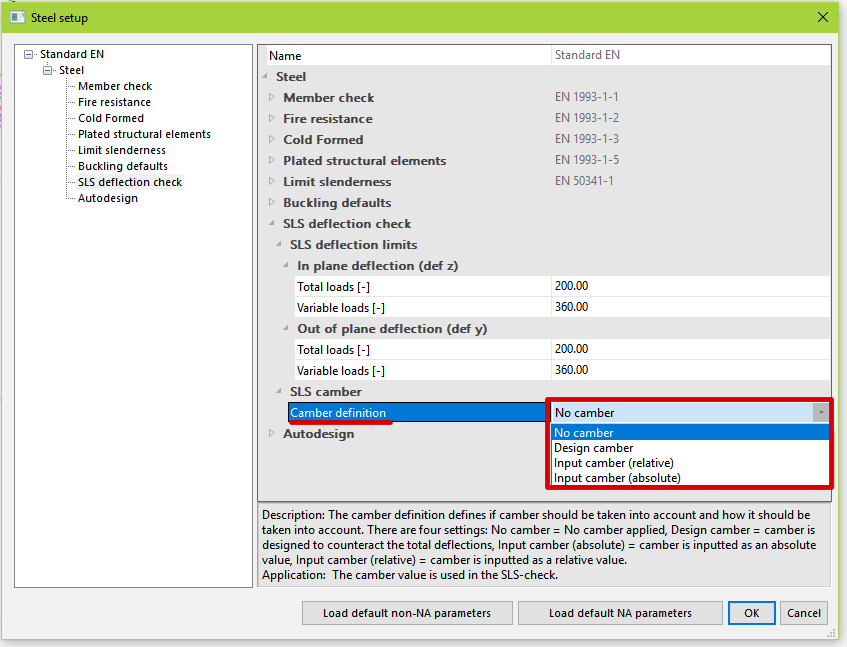
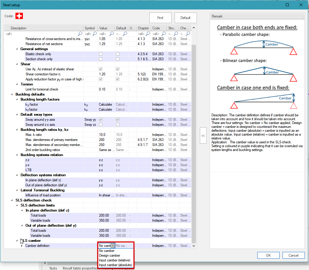
Camber definition
The camber can be defined on two places within SCIA Engineer:
- Steel setup:
The camber definition defined in the steel setup are applied on steel members that are using the default buckling groups or are using a buckling group in which the setting "Camber definition" = From setup.
Eurocode:
SIA-code:
The camber definition in the steel setup contains four settings:
- No camber: no camber defined.
- Design camber: camber is designed by SCIA Engineer based on the acting maximum deflections.
- Input camber (relative): manual input of camber in relative values (camber = def z span length divided by manually inputted relative value).
- Input camber (absolute): manual input of camber in absolute values.
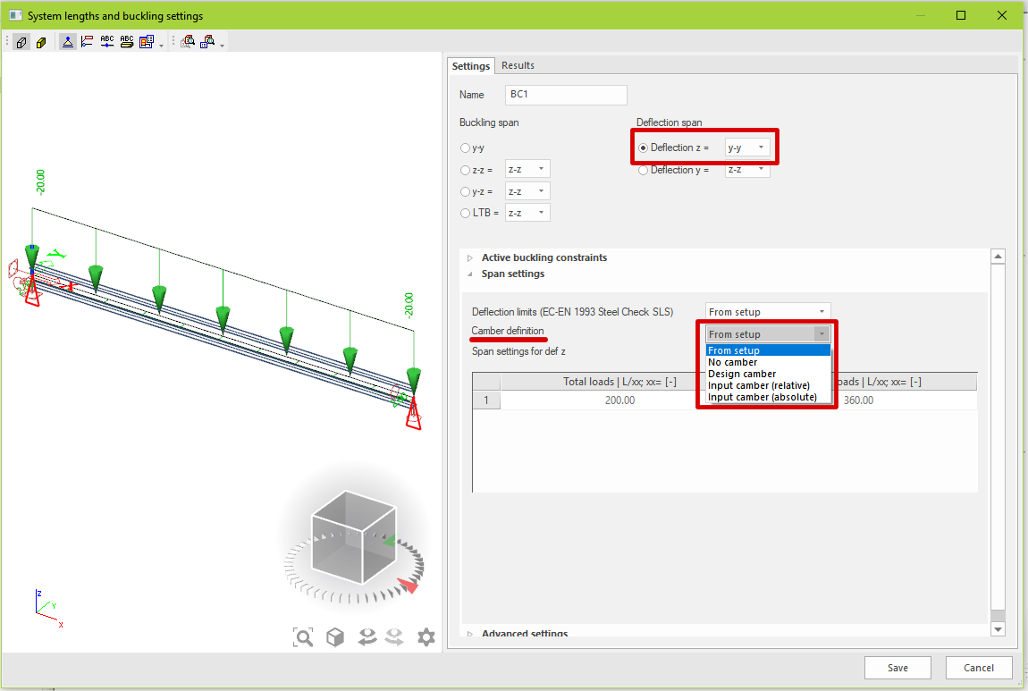
- Buckling groups (via system lengths and buckling settings):
The camber definition can also be defined within a buckling group for deflection z only.
All the members that are using that buckling group will use the same camber definition.
Via the setting within it called "Camber definition" the user can choose from five settings:
- From setup: camber definition from the setup is used.
- No camber: no camber defined.
- Input camber (relative): manual input of camber in relative values (camber = def z span length divided by manually inputted relative value).
- Input camber (absolute): manual input of camber in absolute values.
Camber curves
Within SCIA Engineer three possible camber shapes are supported depending on the type of span:
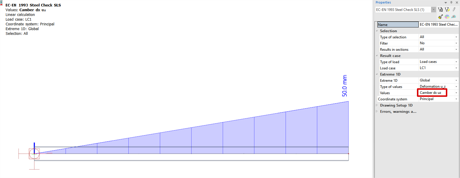
- Deflection z span with one end fixed (=cantilever span):
Linear camber shape
In case the deflection z span only has one fixed end, a linear camber shape is used in which the camber value at the fixed end is 0mm and the camber value at the free end has the maximum value.
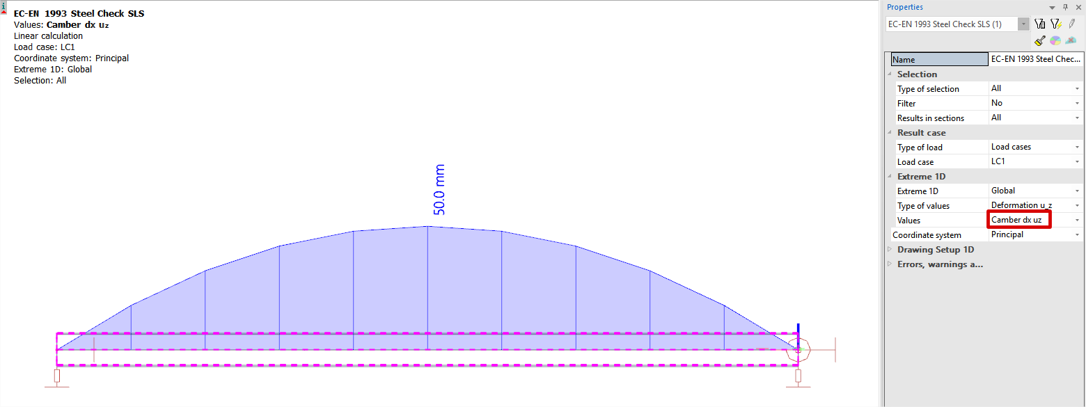
- Deflection z span with both ends fixed (=simply supported span):
a) Parabolic camber shape
In case the deflection z span has two fixed ends and the camber shape is set to "parabolic", a parabolic camber shape is used in which the camber value at the fixed ends are 0mm and the camber value in the middle of the span has the maximum value.
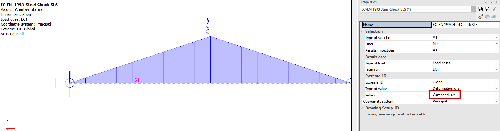
b) Bilinear camber shape (R19.1 or newer)
In case the deflection z span has two fixed ends and the camber shape is set to "bilinear", a bilinear camber shape is used in which the camber value at the fixed ends are 0mm and the camber value in the middle of the span has the maximum value.
It is important to mention that camber is inputted or designed for uz,max according to the local coordinate system (LCS) of the member (coordinate system in SLS-check = Member). This means that the maximum camber value is obtained in the z-direction of the member LCS, if the coordinate system in the SLS-check is set to Principal the camber value is transformed to the principal coordinate system of the cross-section.
Open topic with navigation