![]()
|
||
|
|
||
This chapter introduces the entire service in general and two functionalities (Convert and Align) in detailed.
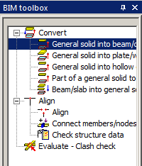
Not all entities imported from another file format can be imported directly as SCIA Engineer native members. In these cases we import the elements as general solids which must be converted to the native members. This is possible by means of the functions described below. Sometimes the analysis shape cannot be the same as the shape of the general solid. Therefore, the proper shape is kept as the structure shape with the General mode.
This function is for entities which have the character of a 1D member. Both prismatic and tapered ones are supported. There are two options for the recognition algorithm – Automatic and Detect straight prismatic beams. The main difference between the two options is the calculation of the member system line (see Reference Guide for detailed explanation).
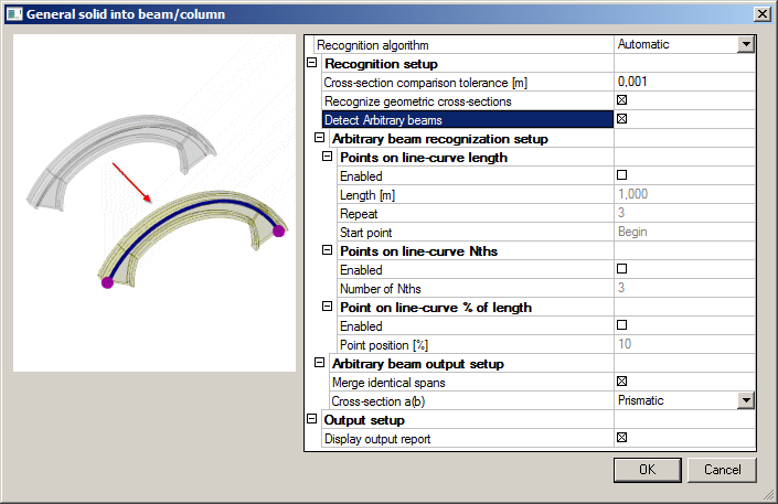
Cross-section comparison tolerance [m]
defines the maximal allowable distance of two points to determine if a new cross-section is created by the recogniser or if an already existing cross-section from the project database is used.
Recognize geometric cross-sections
if ON the recogniser tries to create a profile from the Geometric shape group. If OFF a general cross-section is created.
Detect arbitrary beams
if ON the algorithm tries to detect the variability of profile along the beam length and creates an arbitrary beam.
recognises the shape of the cross-section in specified length intervals.
Points on line-curve Nths
recognises the shape of cross-sections in points which are defined in N-ths of the beam length.
Points on line-curve % of length
recognises the shape of cross-sections in places which are defined with percentage of the beam length.
Merge identical spans
if ON all spans with identical cross-section are merged into one.
Cross-section a(b)
Prizmatic – a span has assigned only one cross-section.
Two Css – a span has different profile on each end.
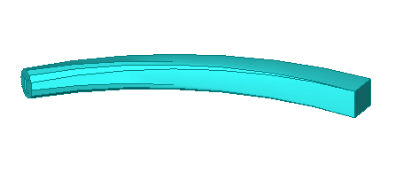
| Detect arbitrary beams | yes. |
| Points on line-curve length | enabled. |
| Cross-section a(b) | two Css. |
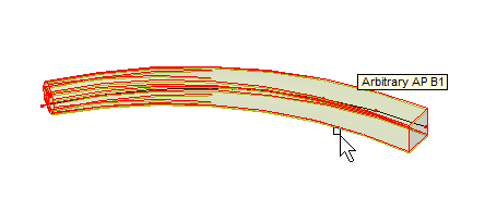
| Detect straight prismatic beams. | |
| Detect arbitrary beams | yes. |
| Points on line-curve length | enabled with Repeat -5. |
| Cross-section a(b) | two Css. |
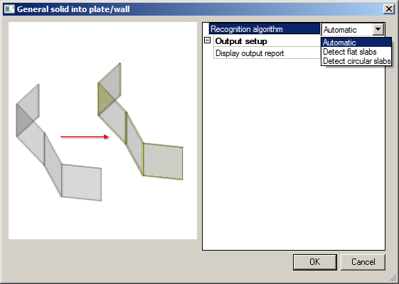
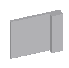
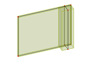
This function is for entities which have the character of a 2D member. Only slabs with a constant thickness are supported. There are three options for the recognition algorithm – Automatic, Detect flat slabs and Detect circular slabs. The main difference between them is the calculation of member system line. Automatic – detects all possible flat slabs in a solid (see Example 1).
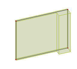
Detect flat slabs
creates only flat slabs in a plane of a solid (see Example 1).
Detect circular slabs
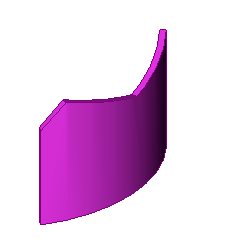
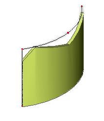
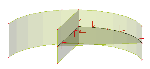
converts a curved solid into a circular slab (see Example 2).
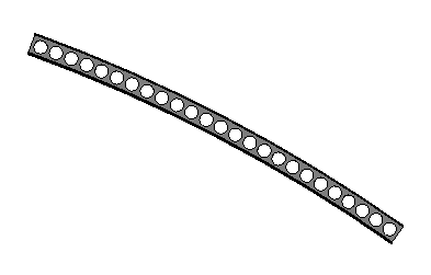
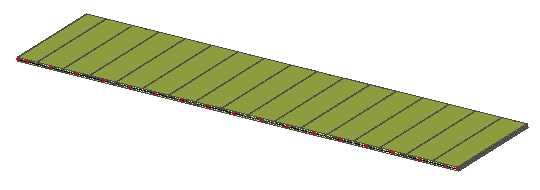
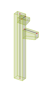
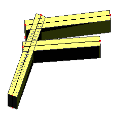
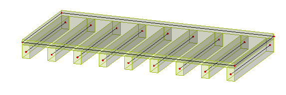
This function is mainly for AllPlan interface for an entity which has a character of hollow core 2D member. The result in SCIA Engineer is a prefab slab with beams inside.
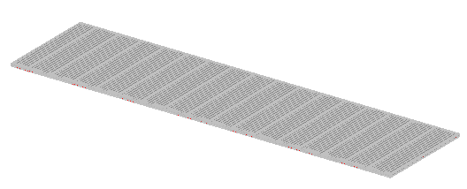
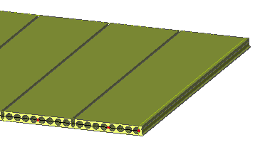
Detailed view at a hollow core slab part.
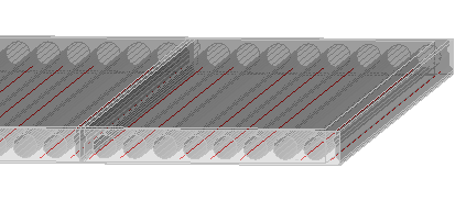
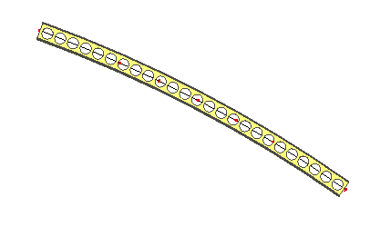
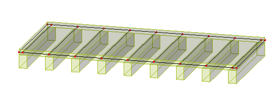
A detailed view of the beams with the hollow core profile.
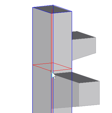
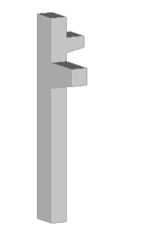
For complicated solids which have a character of a group of more members. This allows for converting only a part of a solid (manually defined) into SCIA Engineer native 1D and 2D members. First, it is necessary to choose if the part is to be converted into a beam or a slab. Only one of the options Recognize beams or Recognize slabs can be selected.
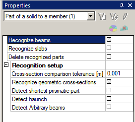
Recognize beams
if ON a beam will be generated from the selected part.
Recognize slabs
if ON a slab will be generated from the selected part.
Delete recognized parts
if ON the original part of a solid will be removed. If OFF the solid is not changed after converting of the selected part into a member.
Cross-section comparison tolerance [m]
defines the maximal allowable distance of two points to determine if a new cross-section is created by the recogniser or id an already existing cross-section in the database of the project is used.
Recognize geometric cross-sections
if ON the recogniser tries to create a profile from Geometric shape group. If OFF a general cross-section is created.
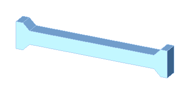
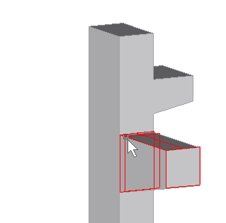
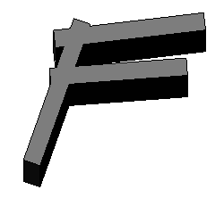
Detect shortest prismatic part
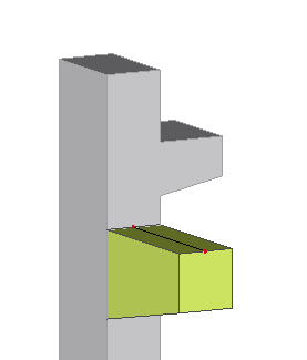
if ON, only the prismatic part of arbitrary solid is detected for conversion (see fig.1).
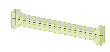
If OFF, the part of solid for converting is taken from the beginning (see fig.2).
Fig.1
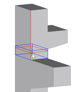
Fig.2
Detect haunch
if ON the algorithm tries to detect the variability of profile and creates a haunched beam (see the following example).
Detect arbitrary beams
if ON the algorithm tries to detect the variability of profile and creates an arbitrary beam.
Structural shape of native 1D and 2D members is converted into general solids. If the entity has an opening, subregion or haunch the result shape is made without any information about these add data.
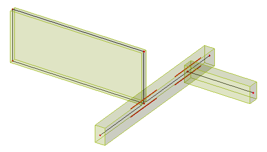
Lots of imported models are not connected, for example after an import from the IFC file. The reason is that some IFC files with the coordination view schema contain information only about the volumes of entities. 1D member axes and 2D member system planes are generated during the import to SCIA Engineer.
See the detailed description in the next chapter.
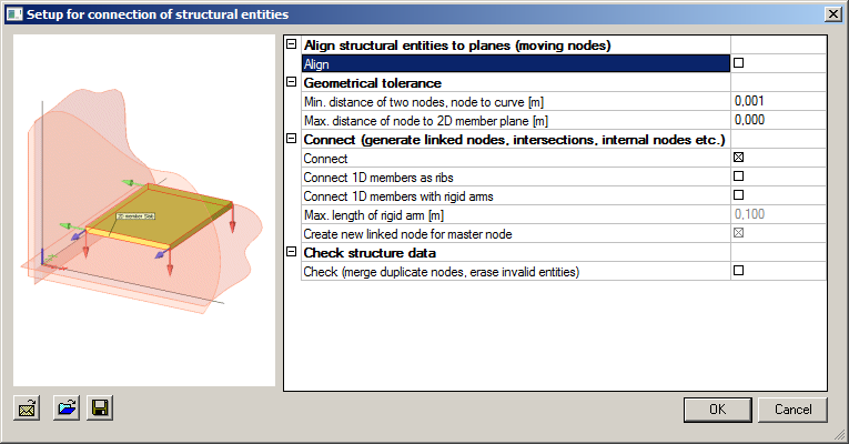
The first part of this dialog is Align. In fact it is the same functionality as the function Align which is described in the separate chapter. The reason for doubling of this function is keeping the original functionality simultaneously with the new one. It does not have all options as the new Align itself.
The next group is Geometrical tolerance which is also in the dialog Setup > Geometry/Graphics. If a user changes the values in one dialog, the value is automatically changed in the second one.
Some types of connection from the group Connect can be done with separate functions. But this is the only place where all connect functions are together.
The last part Check structure data calls the same dialog as the command in the next sub chapter.
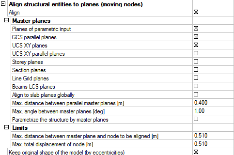
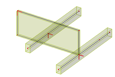
Master planes – planes which are used to move the entities or nodes into.
Planes of parametric input – this option is available only if at least one coordinate of a node is defined by means of a parameter. Then the plane which contains this node is determined as a master plane and other nodes are aligned to this plane.
GCS parallel planes
if ON, entities are aligned in order to fit into any of parallel planes with GCS.
UCS XY planes
if ON, entities are aligned in order to fit into any XY planes of defined UCSs.
UCS XY parallel planes
if ON, entities are aligned to fit into a plane which is parallel with the XY plane of defined UCSs.
Storey planes
if ON, entities are aligned in order to fit into any of defined storey planes.
Section planes
if ON, entities are aligned in order to fit into any of defined section planes.
Line Grid planes
if ON, entities are aligned in order to fit into any plane of the defined line grids.
Beams LCS planes
if ON, 1D members are extended or shortened along their normal axis or moved into LCS plane of other member.
Align to slab planes globally
if ON, 2D members are extended in their plane.
Max. distance between parallel master planes [m]
defines the maximal distance of parallel planes. If the distance of a node is lower than this value, no new parallel plane is created in the node.
Max. angle between master planes [deg]
defines the maximal angle between master planes. If the angle between the existing plane and distance of a node is shorter than this value, no new parallel plane is created in the node.
Parameterize the structure by master planes
this option is available only if at least one coordinate of a structure node is defined by means of a parameter.
Note: LCS planes of 2D members are always used for alignment.
Conflicts
displays a list of entities and nodes which are in conflict with another one.
Master Planes
if any plane is selected it is displayed in blue contour in the graphical window. By means of check box you can select or unselect a particular plane or an entire group of planes.
Log
shows various information, e.g. about limits, etc.
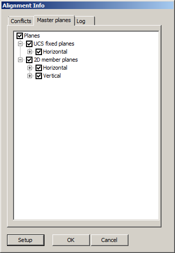
Setup
runs Setup for connection of structural entities dialog again.
OK
confirms the selected Master planes.
Cancel
cancels the function.
Max. distance between master plane and node to be aligned [m]
defines maximal distance when a node is aligned into the master plane. If the distance is bigger the function is not performed.
Max. total displacement of node [m]
defines maximal total displacement of a node when the node can be moved to the master plane. If the total displacement is bigger the node is not moved. This value must not be lower than the value specified above.
Keep original shape of the model (by eccentricities)
if ON, the original shape remains in the original location by means of a defined eccentricity.
The values from this group are used for all geometrical operations.
Min. distance of two nodes, node to curve [m]
defines the minimum distance when two nodes are considered as separate nodes. If the distance is lower than the defined value, the nodes are considered as one.
Max. distance of node to 2D member plane [m]
defines the maximum distance of a node from 2D member system plane. If the node has greater distance from 2D member of which it is a part, the geometry of 2D member is evaluated as invalid.
This group contains functions which allow for connecting members by different ways, such as linked nodes, intersections, rigid arms or joining beams as ribs to a slab.
Connect – if ON, all intersecting entities are connected; this allows for transferring of loads and internal forces between them. Entities are connected in the following way:
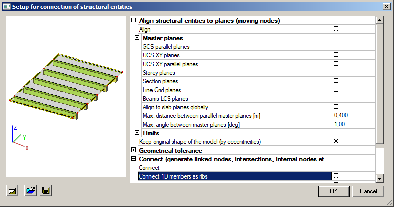
Connect 1D members as ribs – if ON, all selected beams that have the axes in the system plane of the slab are connected to the slab as plate ribs. If the axis of the beam is not in the system plane of the slab it is necessary to use function Align to slab planes globally first.
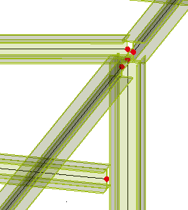
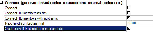
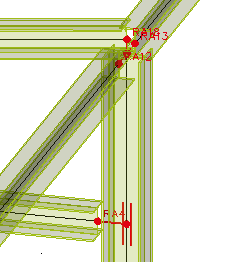
Connect 1D members with rigid arms
if ON, all the nodes of 1D members whose distance is shorter than the values defined in the next option will be connected with a rigid arm.
Max. length of rigid arm [m]
defines the maximum distance of two nodes or a node and an axis of the beam for which a rigid arm will be created.
Create new linked node for master node
if ON, a linked node will be created on the beam which has a node closer than specified by the value for the maximal length of the rigid arm. The linked node is always the master node of the rigid arm.
This option is for situations when the user does not want to change the length of 1D members but he needs to analyse the model. The rigid arm entity connects the structure and transfers internal forces between beams.
Check – see the subchapter below.
It is possible to call this function from various locations. It is here because it is apposite to check model geometry more often as geometrical operations are done. It checks lots of things such as duplicate nodes, free nodes, members with zero length and undefined nodes, duplicate beams or slab, positions of additional data, etc. For more detailed description of this function see SCIA Engineer Reference Guide.
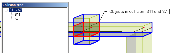
This function checks whether two or more entities (solids, 1D and 2D members, reinforcements) intersect each other. Then new solid is created in the intersection of the entities; this new solid is called collision solid.
Show tree of clashes
if ON, a dialog with a list of all collisions between entities is shown. If you click on the collision of two entities you will see a blue contour around the colliding entities and a red contour around the collision itself - see the picture below. If you click only on the concrete member you will see only the member with blue contour.
Show collision description
if ON, a label of collision is shown in the graphical window.
Show transparent structure
if ON, rendering of structure is set to transparent.
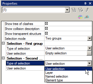
Selection mode
One group - a selection of entities by one criterion,
Two groups - a selection of entities by other criterion than in group one.
In each group it is possible to define the following Type of selection:
User selection
a list of selected elements for clash check.
Layer
a selection of elements just in a layer for clash check.
Named selection
a selection by means of named selection
Element type
a selection by type of entities (1D members, 2D members, general solids or free bars).
Run clash check
runs the check and creates all collision objects.
Delete collision objects
removes all created collision objects.
End clash check
performs the function.