![]()
|
||
|
|
||
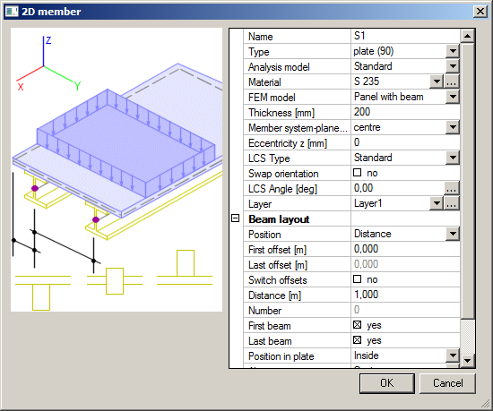
For this type of load panel it is necessary to define properties for both plate and beams. Properties of the panel are the same as for a standard plate. The direction of beams depends on the plate LCS. The beams are always parallel with the local x axis.
Position
- Distance – defines the distance between beams
- Number – defines the number of beams
- Width – defines the width between beams (this type of input is similar to option to Distance but offers different other parameters)
- Generic – defines the location of each beam individually
First offset
- defines the distance between the first beam and the edge of panel
Last offset
- defines the distance between the last beam and the edge of panel
Switch offsets
- swaps the first and last offset
Distance
- defines the distance between beams
Number
- defines number of generated beams
First beam
- defines if the first beam is inserted
Last beam
- defines if the last beam is inserted
Position in plate
- defines the position of beams in plate – inside, outside
Alignment
- defines the alignment of beams
Beams eccentricity Z [mm]
- defines beam eccentricity
Select all beams to generator
- if ON all beams are selected automatically, in OFF the user can select only some of them
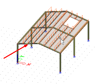
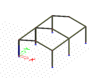
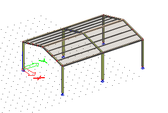
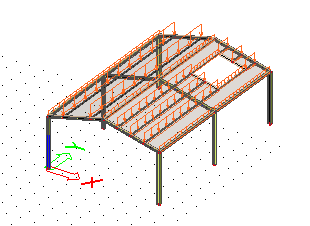
1. Create a simple hall.
2. Run Structure service > Load panel > Panel with parallel beams and input panels on the roof of the hall.
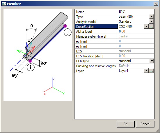
3. Then define beam properties in the Member dialog.
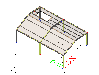
4. Use option Switch offsets to set zero offsets of both panels by a ridge of the hall. I.e. tick Switch offsets and define Last offset as 0.
5. Select one of the panels and uncheck items First beam and Last beam.
6. Select the other and uncheck the beam at the end of the roof.
7. Select one of the panels and input an opening using function 2D member > 2D member components > Opening or Load panel > Load to opening edge (with unchecked option Panel).
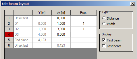
8. Select the other panel, change Beam layout – Position to Generic. A new item Editor is displayed in properties. Run the editor pressing the button with three dots.
9. Change beam positions and confirm with [OK].
10. Go to service Load and define a permanent load case of type Standard.
11. Input Surface load on 2D members on all panels in that load case.
12. Select the panel with the opening and press the action button Load generation in its properties. Line forces are generated on all beams.
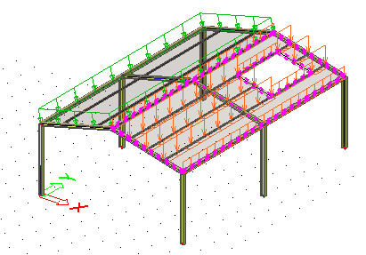
13. Run Calculation to generate line forces on the whole structure.
14. Input a beam between beams on the panel with beams in generic positions.
15. Select the panel and uncheck option Select all beams to generator.
16. Click the action button Update beam selection, select the inserted beam and finish the function.
17. Now the beam is in the panel properties Beams > Included in load gen.
18. Run Calculation again. Load is generated on all beams.