![]()
|
||
|
|
||
First of all the standard SCIA Engineer project must be prepared. Therefore, create a model of a structure with all the necessary aspects of the future optimization taken into account.
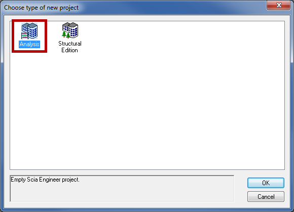
Run SCIA Engineer and create a new project of the Analysis type.
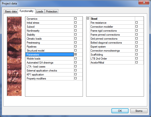
The basic Project data can be filled in according to the picture below:
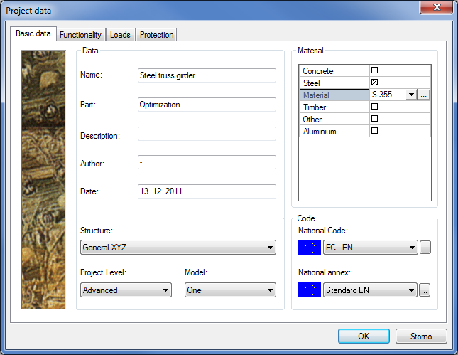
Although the structure is planar, the structure type is set to General XYZ to keep it more general. The project level is set to Advanced, which is a generally recommended setting. The code of this particular project is set to EC-EN with the standard EN annex.
Press OK to confirm the settings and to open a blank project.
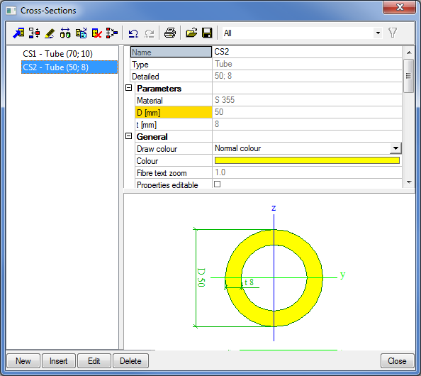
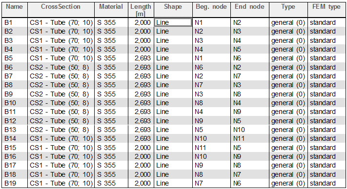
Model the truss girder with 1D members. First, you will be asked to select cross-sections for the current project. Add two tubular cross-sections with the dimensions:
CS1:D = 70 mm; t = 10 mm
CS2:D = 50 mm, t = 8 mm
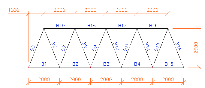
Create the structure according to the following scheme and table:
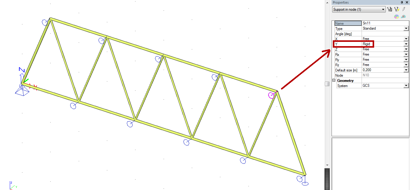
The truss as a whole structure is simply supported. To restrain the lateral displacements, supports in all nodes must be defined to prevent from the deformation in the Y direction.
When the structure is modelled, loads have to be specified as well. The truss girder is subjected to a simple load case with vertical point forces in the bottom nodes. Create a new load case with the action type Permanent and load type Standard.
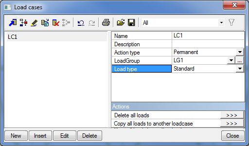
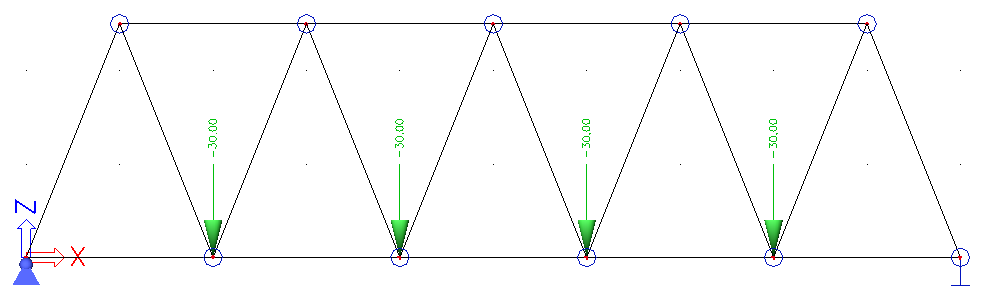
This load case is represented by 4 point forces with the magnitude of -30 kN in the Z axis direction (the load is going downwards).
The structure is calculated using standard functions of SCIA Engineer first. To see utilization of profiles, a unity check can be performed in Steel service, see next picture.

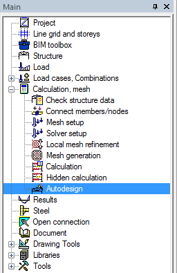
Maximal unity check value 0,69 shows, profiles are too thick. In SCIA Engineer we can use very efficient tool to design cross-sections, resulting in a good utilization of individual members under a certain load. The function is called Autodesign and it can be found under Calculation, mesh group in the Main tree.
Autodesign can be used for various purposes. The Cross-section steel check will be used in this case. This Autodesign function finds an optimal cross-section with respect to the unity check for all members with this cross-section. However, as the change of a profile in a statically indeterminate structure affects the internal forces, the project has to be recalculated. For new internal foces, after recalculation, we can run Autodesign again. The user can do those two steps several times to reach proper cross-section design.
Autodesign is also integrated in optimization loop s of EOT. It means, during iterative search of optimal structure geometry, the program will make design of proper cross-sections. It means, in each iterative step, both geometry and cross-sections will be improved at the same time.
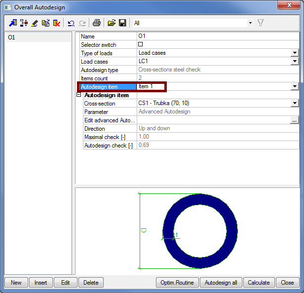
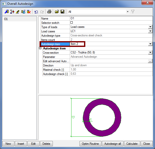
Prepare a new entry (called O1) in the Overall Autodesign library. Select both cross-sections (CS1 and CS2) in the selection dialogue. It means that the items count will be 2.
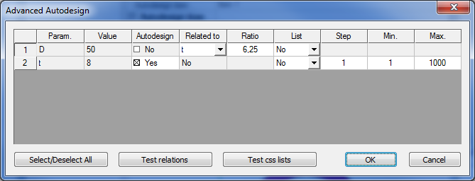
Each cross-section has got two dimensions in their properties – thickness t and diameter D. Both dimensions can be changed upwards and downwards in order to search for the optimum. To optimise both variables in one run, we will keep a fixed ratio between D and t. Advanced Autodesign is used for this.
It is not needed to do the Autodesign at this moment. EOT application will use this stored setting afterwards.
The optimization is based on parameters. SCIA Engineer allows the user to prepare lot of different kinds of parameters, which can be assigned to various entities and/or properties.
In this particular example we want to adapt the shape of the upper chord to get the minimum mass of the structure. This means that some nodes will change their positions (z-coordinates). Therefore, we will to make a set of parameters and we will assign them to properties of nodes.
To make parameters available, we have to switch them on in functionality setting:
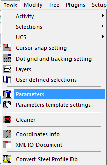
Then, let us open parameters library under Tools > Parameters. New items can be added with the button New in the top left or the bottom left corner (both these buttons do the same).
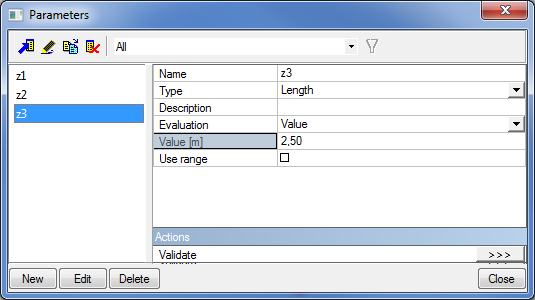
Prepare three parameters which will specify the Z coordinate of nodes of the upper chord. As we need a symmetric structure three parameters will be sufficient. The type of parameters is set to Length, Evaluation to Value and the default value is 2.5 m at the moment.
Assigning parameter to a node is simple. Just select a node and then, assign the parameter to the value of this property of selected node.
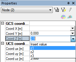
Select the outside nodes N6 and N10 and change their Coord Z to z1.
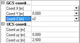
Select the inner nodes N7 and N9 and change their Coord Z to z2.
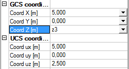
Select the the middle node N8 and change its Coord Z to z3.
When the value of particular parameter is changed, the structure reacts immediately. However, let us assign this job to EOT. It shall calculate the correct value for each of the parameters.