![]()
|
||
|
|
||
In this step load cases are created for each load group. This can be done in a standard way in the Load cases dialog.
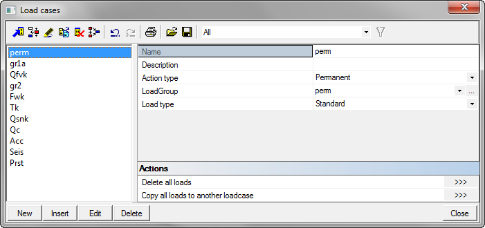
| Name | Action type | Load group | Load type |
|---|---|---|---|
| perm | Permanent | perm | Standard |
| gr1 | Variable | gr1 | Static |
| Qfvk | Variable | Qfvk | Static |
| gr2 | Variable | gr2 | Static |
| Tk | Variable | Tk | Static |
| Fwk | Variable | Fwk | Static |
| Qsnk | Variable | Qsnk | Static |
| Qc | Variable | Qc | Static |
| Acc | Accidental | Acc | Static |
| Seis | Seismic | Seis | Static |
| Prst | Permanent | Prst | Prestress |
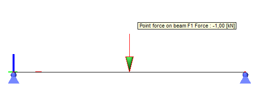
After definition of all load cases, loading is defined. In this example, as we already mentioned at the very beginning, we will define only 1KN point load in the middle of the beam, for every load case.
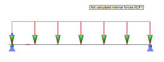
The only difference is prestressing load case Prst, where we will define line load, shown on the picture below, with the intensity of -0,2Kn/m.
Whenever a certain load case is assigned to a certain combination, aditional restrictions are implemented for load case in Load cases dialog. It will still be possible to change the Load group parameter to something else, but the user may select only load groups with the same Structure parameter or independent variable load groups for accidental and seismic loads. By pressing the three dots edit button, the Load groups dialog is displayed, but with filtered content. If a load case is not assigned yet, the user may freely change load group.