|
||
|
|
||
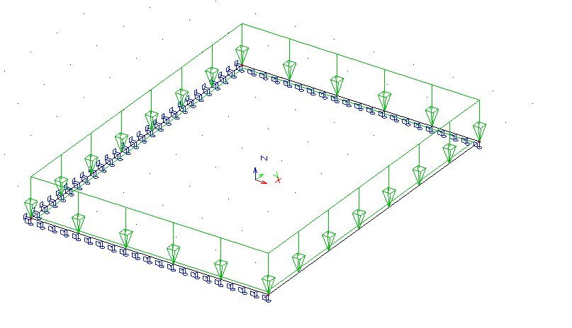
We can demonstrate the basic possible workflow for reinforcement design on example similar to the previously used for demonstrating internal forces. It is a concrete plate defined in XY project, supported according to the picture. It is made from concrete C25/30 and is 200 mm thick. It is loaded with self weigh in LC1 and with constant surface load of 10 KN/m2 in LC2. Results will be described on combinations which contain both previous load cases.
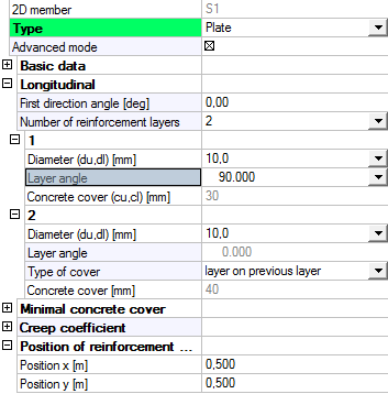
The reinforcement design will be shown only for lower reinforcement in the direction of the y axis of the member LCS, where we expect more amount of reinforcement. We need also redefine design defaults settings, where the reinforcement 1 direction is identical with the X axis of the member LCS. This will be done by defining member data and setting Layer angle parameter for first direction to 90 degrees. This layer will be now closer to the surface and will decrease the amount of designed reinforcement little bit. We could change the reinforcement direction also by adjusting the first direction angle and rotating the whole reinforcement system.
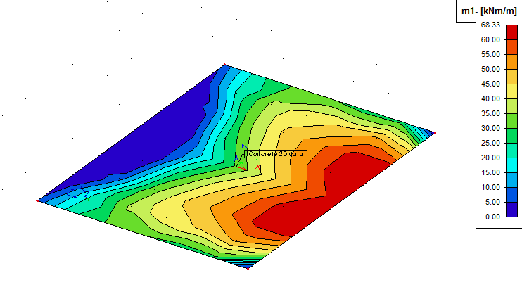
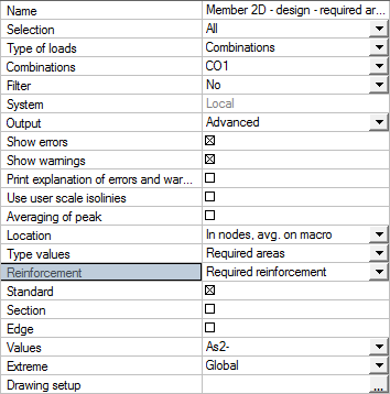
On the picture below there is magnitude of m1-, which will be determining for the reinforcement design. We will use location In nodes, avg. on macro and isobands will be used for presentation.
Now we are ready to run ULS reinforcement design by adjusting ULS service properties and pressing Refresh action button. After this dialog with a progress bar will appear and then final message with conclusion of the design will be displayed. After confirmation of this dialog, the results will be displayed.
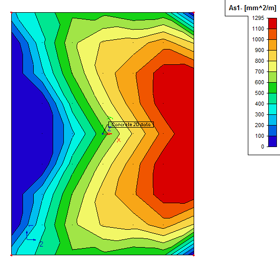
For better orientation in the design process, all types of reinforcement will be shown in the table below.
|
Required reinforcement |
User reinforcement |
|
|
|
|
Additional reinforcement |
Total reinforcement |
|
|
|
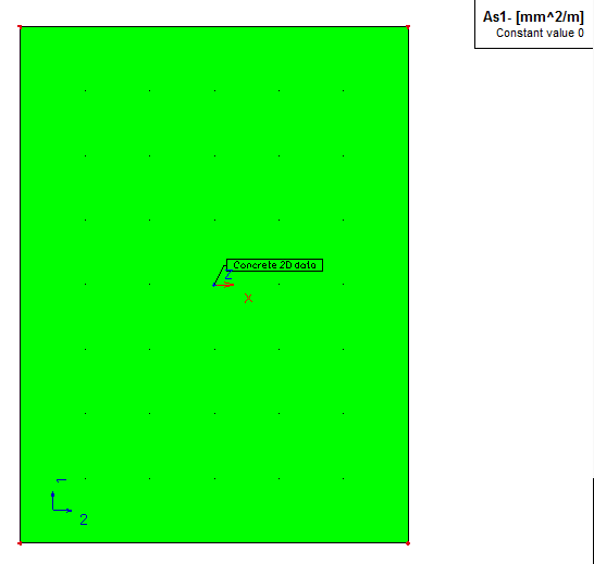
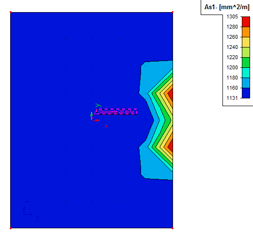
As we can see, no user reinforcement is defined yet. Therefore amounts of required, additional and total reinforcement are equal.
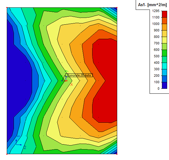
We can also check the design values in preview window. The user may switch to brief, detailed or advanced mode, as we did in this example. We can see that maximal amount of reinforcement for lower surface and direction 1 is designed to 1295 mm2/m.
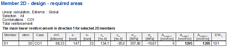
Now the user has to decide how he wants to reinforce the designed member. Whether he wants to define each reinforcement layer manually or if he wants to use automatic definition of reinforcement from concrete member data. The second possibility is much common and more useful, so we will show this one. The user has to activate User reinforcement check box in the concrete data first. This will enable him to define Basic distance of bars.
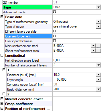
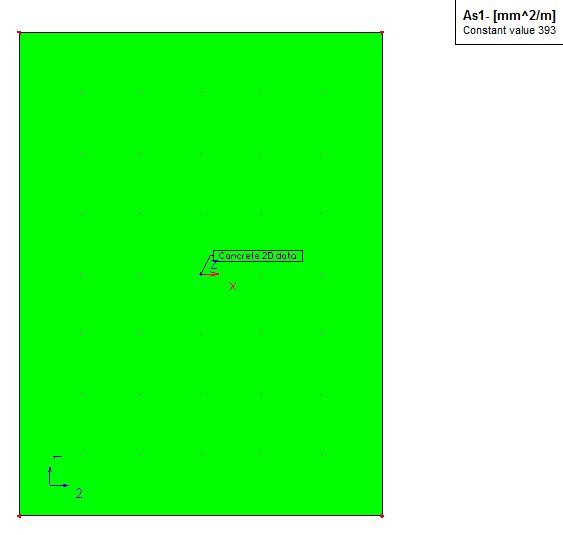
After this, the amount of user reinforcement is determined directly from concrete member data and the user may simply adjust it by changing appropriate parameters (diameter, basic distance). Default values are loaded from Concrete setup dialog, which might be changed in Design defaults. Let’s see the differences in designed amounts of reinforcement just after activating the user reinforcement check box.
|
Required reinforcement |
User reinforcement |
|
|
|
|
Additional reinforcement |
Total reinforcement |
|
|
|
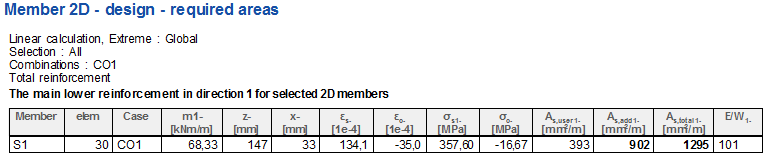
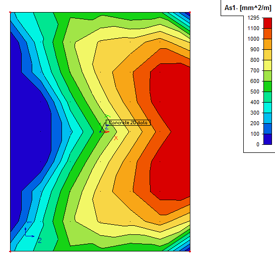
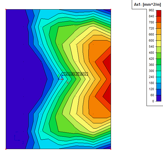
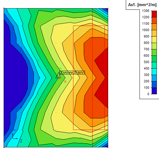
Now the user reinforcement has non-zero values and accordingly to this change, amount of designed additional reinforcement has been changed too. However the reinforcement amount defined is not sufficient enough, so we have to adjust the concrete data to fulfil the requirements. Before this we can check the preview window for more information.
It is clear from here, that additional amount of 902 mm2/m has to be added to fulfil the required amount. Let’s redefine the reinforcement diameter to 12 mm and basic distance to 100 mm. Now we get these results.
|
Required reinforcement |
User reinforcement |
|
|
|
|
Additional reinforcement |
Total reinforcement |
|
|
|
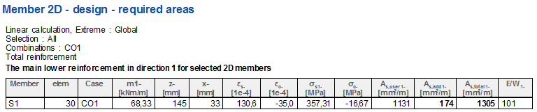
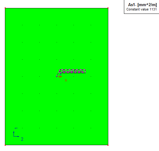
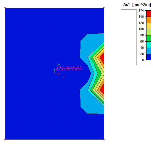
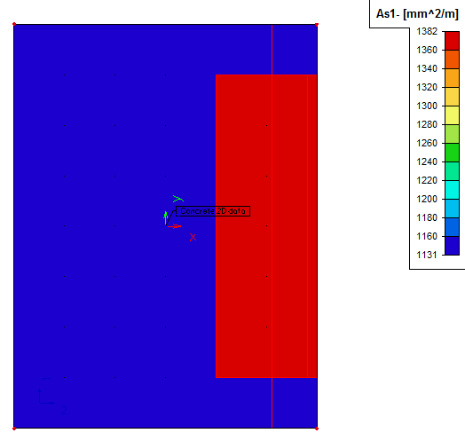
From this results we can see that the defined reinforcement is sufficient on mostly whole 2D member area. However there is requirement for additional 174 mm2/m of reinforcement on the right side of the designed member. We don’t want to define more reinforcement for whole member area and we will handle this requirement afterwards, by creating a separate reinforcement polygon.
We can now proceed to creating practical reinforcement from user reinforcement. We have the User reinforcement check box active, so we can simply double click the Reinforcement 2D item in the concrete tree. The dialog below will be displayed and a new practical reinforcement will be created from the user reinforcement previously defined by concrete 2D data.
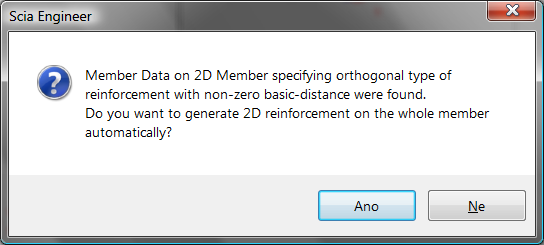
After confirmation of this dialog, practical reinforcement is created and input into 2D member. Now we will also define additional reinforcement to cover the requirement on the right side of the member. Let’s double click the 2D Reinforcement again and define it.
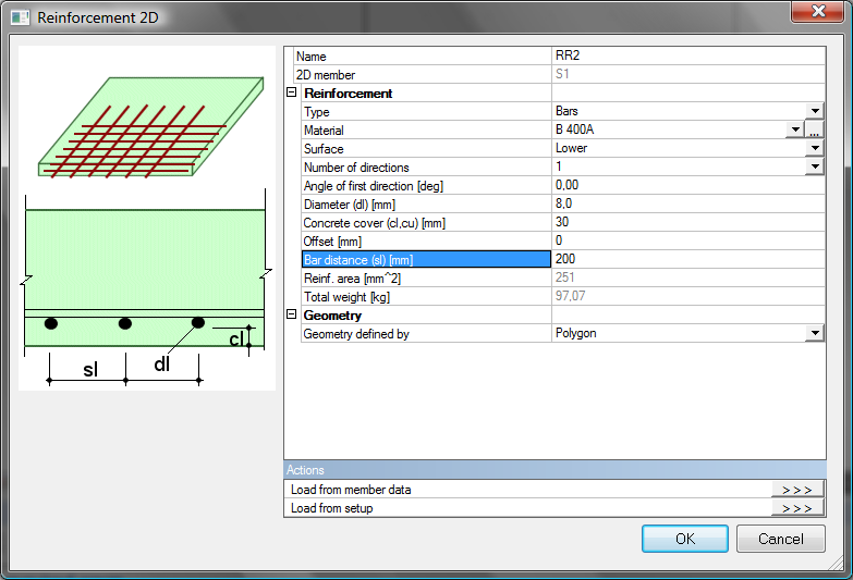
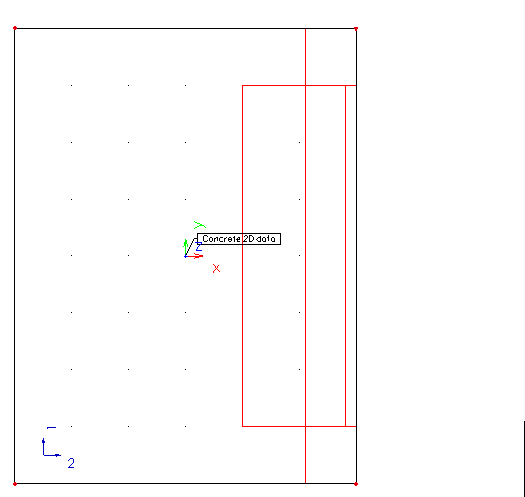
The designed 2D member has now two reinforcement polygons defined for lower surface and direction 1. One is on the whole 2D member and the second one is only on the mentioned right side. See picture below.
|
Required reinforcement |
User reinforcement |
|
|
|
|
Additional reinforcement |
Total reinforcement |
|
|
|
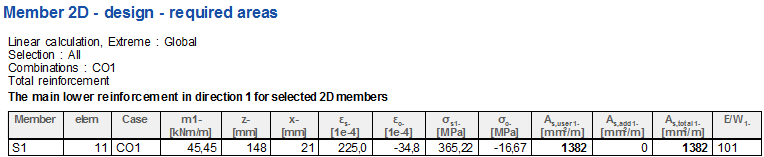
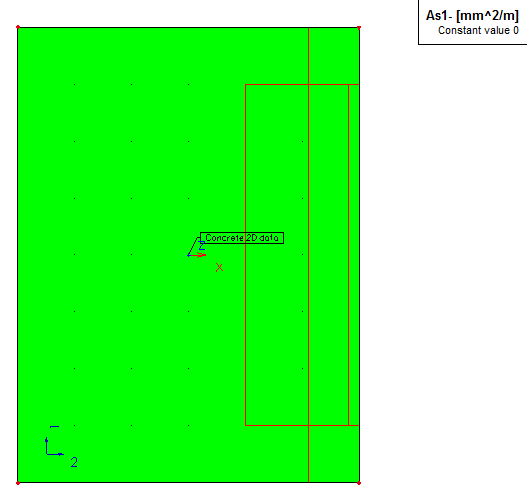
At this time we have fulfilled the requirements for direction 1 at the lower surface. No additional reinforcement is needed. The upper surface and other directions might be handled in a similar way we have shown here.