![]()
|
||
|
|
||
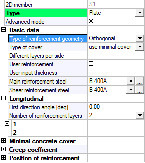
In this group basic attributes and parameters for reinforcement design are located. As you can see from the picture the user can edit reinforcement geometry, type of concrete cover and reinforcement materials here. Also Different layers per side, User reinforcement and User input thickness attributes are here.
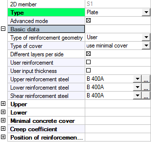
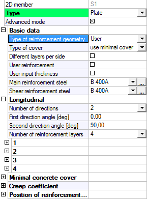
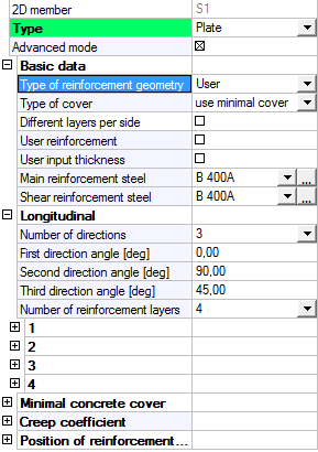
There are two types of reinforcement geometry in SCIA Engineer:
|
Orthogonal |
User 2 directions |
User 3 directions |
|---|---|---|
|
|
|
|
Minimal difference between two reinforcement directions defined directly by user, must be 30 degrees. If the difference is smaller, then the reinforcement design will end up with Error 61 (General error in input data).
It is possible to change the way concrete cover is calculated. Two basic types of cover are supported:
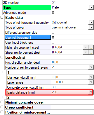
User reinforcement is defined by new parameter Basic distance in Longitudinal folder, where user defines the axial distance of reinforcement bars. It is possible to define different value for each reinforcement direction.
It is possible to set this attribute ON only in the case that there is no user reinforcement defined by 2D region or Free bars on selected 2D member or its sub region.
User reinforcement defined by Member data is the same for the whole 2D member surface. If the user wants to change the Basic distance value only on a part of the 2D member, then he needs to create sub region where this parameter may be defined separately.
If the user reinforcement is already active on a certain member and the user defines user reinforcement by 2D region or by free bars, then the user reinforcement defined in Member data will be deleted.
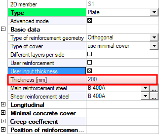
SCIA Engineer software enables to set different thickness for 2D member or its sub region than is defined in the model. The big advantage of this feature is that it is possible to run reinforcement design for different thickness, without the need of deleting calculation results together with internal forces. The importance of this function is directly proportional to the size of the structure, as the calculation of internal forces for large projects may take very long time. What is important is that the user must remember the fact that the self weight of the changed member is not adjusted by the changed thickness by this function and remains the same as originally defined.
The user defined thickness of a 2D member or its sub region can be edited by new parameter Thickness. This parameter will be displayed after switching on the attribute User input thickness.