![]()
|
||
|
|
||
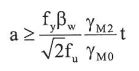
The stiffener thickness th is designed according to the resistance of the joint. The design resistance of the stiffener is equal to the design resistance of the weld Fw (See also chapter: "Calculated from connection resistance")

with:
The final thickness of the stiffener is multiplied by the ratio of fy,beam/fy,stiffener to assure that the stiffener will be strong enough to transverse the force from the beam.
In case conditions for aplying the additional resistance the the "Column web in shear" component (for further info see "Column web panel in shear" chapter) are fulfilled, the calculated stiffener thickness is taken equal to the thickness of the bottom flange of the beam.
For calculation of weld sizes of stiffeners perpendicular to the column/beam flange, the same method described "Minimum for full strength" in chaper Calculation of flange weld size, is used. The calculation is based on the Ref. [35] - ECCS N° 126. The final formula is derived as:
with
Each stiffener thickess and weld size is calculated separately, based on the used material.
Thickness of the web doubler is always taken as the inputted thickness of that component. Weld size of a web doubler with relation to the article EN 1993-1-8, Art 6.2.6.3 (8), is based on the type of the web doubler:

