![]()
|
||
|
|
||
In this second example the principles of Member Data are explained. Member Data can be assigned to elements within SCIA Engineer and allow the user to directly access the Input Dialog of SCIA Design Forms.
The Design Form of the previous example is therefore extended with additional parameters which can be set by the user of the Form.
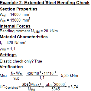
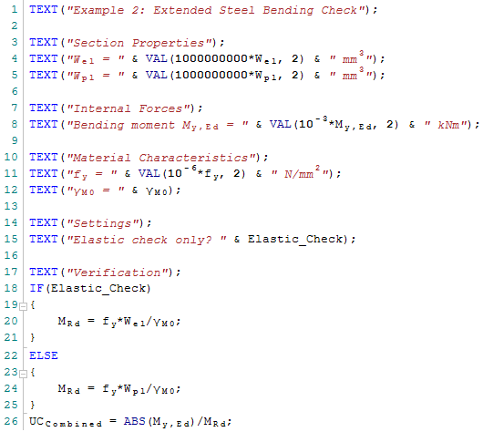
The following pictures show the output of the Design Form and the related script:
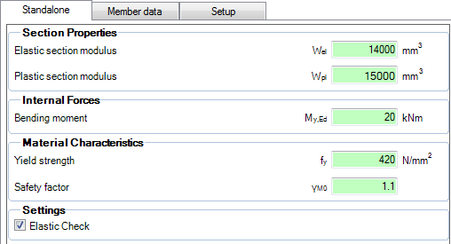
The Form uses the following variables as manual input when running standalone:
The main differences with the previous example are the following:
- In addition to the elastic section modulus Wel also the plastic modulus Wpl is used
- Using a Checkbox the selection between the elastic and plastic modulus is made
- The resistance is extended with a safety factor γM0
The purpose of this example is to illustrate how Member Data can be defined which contains the additional parameters used in this Form (the Checkbox and the factor γM0). In general, Member data allows the user to access any parameters directly through the Design Form dialog.
Step 1: Put the .CLS file in the 'User' folder
Step 2: Set the ESA ID for each variable which needs to be linked
Step 3: Optionally define Member data
Step 4: Define the Check Header
Step 5: Export the Form to a .CLC
Step 6: Import the .CLC into the Check Manager
Step 7: Optionally edit the Check Header and provide icons
Step 8: Execute the Check
Step 9: Evaluate the Results
Step 10: Optionally review the DataCache and Trace file