![]()
|
||
|
|
||
As demonstrated in the previous examples, upon executing the check from within SCIA Engineer, an export will be made of all relevant model data (cross-sections, materials, internal forces ...) to the 'DataCache'.
In this first step, the ESA ID's for the relevant variables which will be linked are defined in the Form.
Launch the SCIA Design Forms Builder and open the Form Manual_Example_3.CLS.
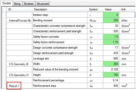
Within this Form, the grid on the 'Calculation' tab shows the double values to be manually inputted in a green color:
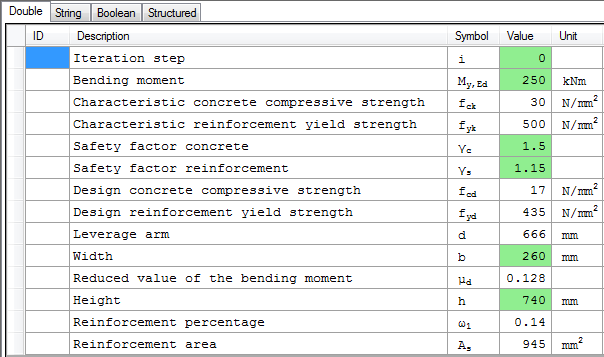
The iteration step i concerns a variable used internally by the Get_w1 function and is thus not a value to be inputted.
The safety factors γc and γs concern properties which do not exist in the DataCache, so these will be set later on as Member data.
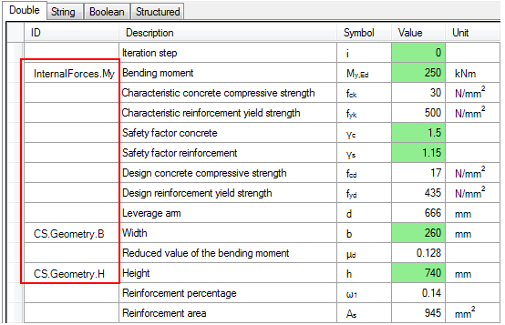
Using the basic information from Annex B the following ID's are found to represent the data needed by the form:
|
ESA ID |
Variable |
|---|---|
|
InternalForces.My |
Bending moment about the principal y-axis |
|
CS.Geometry.B |
Width of rectangular cross-section |
|
CS.Geometry.H |
Height of rectangular cross-section |
These ID's are inputted within the grid of the Form:
This covers the basic inputs however the libraries are referenced directly within the script.
Within this example, two libraries are used. The standard Concrete material library is pointing to the following Target IO node ('Dialog' tab):

The custom library for the Reinforcement material is pointing to the following Target IO node:

These Target IO nodes are available purely during the standalone run of the Form and are being used directly on lines 426 & 427:
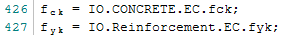
Both Target IO node strings can in fact be freely defined by the author of the Form.
However, the DataCache does not contain this structure, so the above two lines are not valid in case the Form is run from within SCIA Engineer. When running the Form from within SCIA Engineer it is thus required to set the correct IO structure for these variables so they are read from the DataCache.
Instead of just providing the solution, let us walk through the DataCache to see what is available and how the fck and fyk variables can be correctly retrieved both in the standalone run and in the linked run.
In this subpart of the example the EMD Loader is used to examine what is available in the DataCache. Annex A also contains information on the EMD Loader.
Using SCIA Engineer the DataCache files will be generated after which their content will be examined from within SCIA Design Forms.
- First of all, close SCIA Engineer in case it was still open.
- Next, launch SCIA Engineer using the Command line switch -OCEMD. This switch makes sure the required .emd files will be generated when executing the Check. Refer to Annex A for more information.
- Open the file Manual_Example_3.esa.
- Perform a Linear calculation to refresh the results.
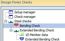
- Go to the  service.
The project file in this case contains two Concrete members. Since the Checks defined in the previous examples require members made out of Steel these Checks will not work with these members.
- Therefore, open the Check Manager.
- Select the Bending Check and change its material from Steel to Concrete:
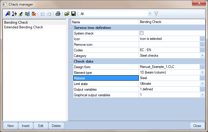
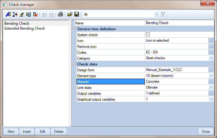
- Close the Check Manager with [Close]
- In the Service, select the  and set the following properties:
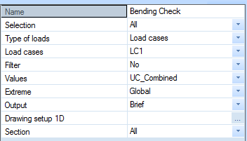
- Press the Refresh action button.
No results are shown, it seems as if nothing happened, but this is correct and caused by the usage of the -OCEMD switch. This switch generated the .emd files but does not run any check and thus results are neither generated nor shown.
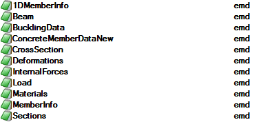
- Using a file explorer like Windows Explorer, navigate to the TEMP folder of SCIA Engineer and locate the subfolder ESA_Model_Data
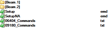
Now go to the subfolder Beam.1. This folder contains all input data (.emd) for this member.
When looking inside the Materials.emd file using a standard text editor like NotePad the data for the Material for this beam can be found:
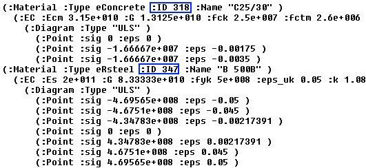
The file shows that there are two materials, Concrete and Reinforcement Steel. Each of these materials has its own ID by which it is referenced to in other parts of the DataCache.
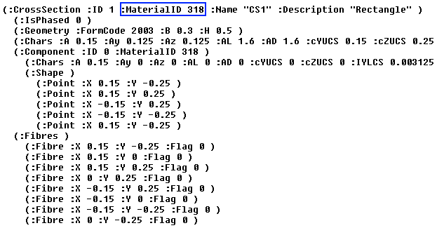
Looking for example in the CrossSection.emd file it can be seen that the cross-section refers to the Material ID of the Concrete material.
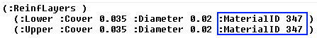
In the same way the Beam.emd file shows the reinforcement layers which refer to the Material ID of the Reinforcement Steel.
To illustrate exactly how the DataCache is seen by SCIA Design Forms the EMD Loader will be used.
- Open the SCIA Design Forms Builder and create a new empty Form.
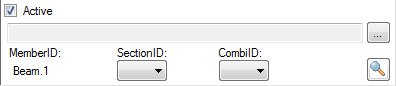
- Go to the 'Dialog' tab and add the  component to the Standalone dialog.
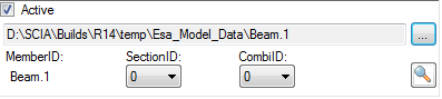
- In this component, use the  button and navigate to the TEMP folder of SCIA Engineer and further down to the ESA_Model_Data and Beam.1 folder:
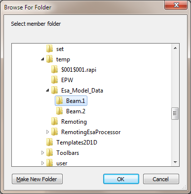
The folder on the screenshot will differ from your own folder and depends on the installation and version of SCIA Engineer.
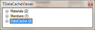
- Use the Spyglass button  to see the contents of the DataCache
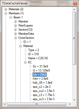
- The tree structure can now be used to navigate through the DataCache. For example the fck value for the (Concrete) Material of the Cross-section of the Beam can be found here:
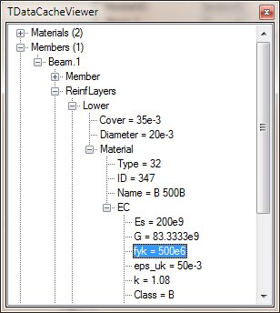
- In the same way the fyk value of the Lower Reinforcement Layer of the Beam can be found here:
- Close the DataCacheViewer using the close  button.
- Now go to the 'Calculation' tab.
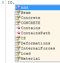
- In the editor, type IO. (Including the dot)
Immediately an Intellisense window will be shown which shows the content of the DataCache:
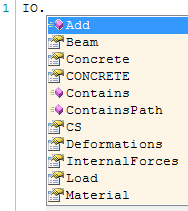
The EMD Loader has loaded the content of the .emd files into the IO Structure so it can be directly accessed here.
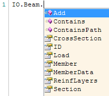
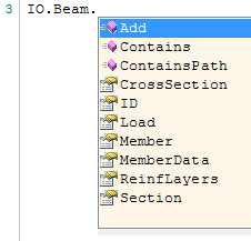
- Select Beam from the list and again type a dot. A new Intellisense will be shown:
We are now accessing the DataCache node of the Beam. As shown above we need to access the material of the cross-section thus select CrossSection from the list again followed by a dot.
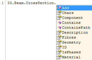
The Intellisense shows the data within the CrossSection node. Now select Material again followed by a dot.
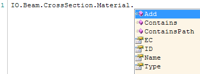
Now we are really accessing the material of the Cross-section i.e. the Concrete.
- Select EC followed by a dot.
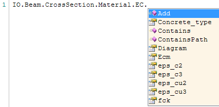
Here we now see all Concrete properties as shown in the Materials.emd file and the fck can be selected.

- In the same way the Reinforcement material can be accessed. On a new line type IO followed by a dot.
- Select Beam from the list and again type a dot.
- Select ReinfLayers from the list and again type a dot.
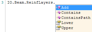
- Select Lower from the list and again type a dot.
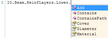
- Now select Material again followed by a dot.
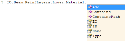
- Select EC followed by a dot.
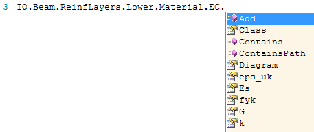
Here we now see all Reinforcement Steel properties as shown in the Materials.emd file and the fyk can be selected.

This concludes the Intermezzo on the usage of the EMD Loader. It illustrated how to generate the .emd files and how to navigate through them using the EMD Loader.
Before continuing, please do the following:
- Within SCIA Engineer, in the Check Manager, change the material of the Bending Check back to Steel.
- Close SCIA Engineer.
- Within SCIA Design Forms, close the new Form containing the EMD Loader.
For the actual example, the Form contained the following two lines for reading the IO Structure during a standalone run:
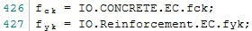
The above Intermezzo has shown that, in order to read the data from the DataCache, the following references are needed:
fck = IO.Beam.CrossSection.Material.EC.fck
fyk = IO.Beam.ReinfLayers.Lower.Material.EC.fyk
For both variables the IO Structure for a standalone run is different than for a check run from SCIA Engineer. When running standalone it uses the IO Structure as defined in the Target IO node while when running from SCIA Engineer it should be taken from the DataCache export.
It is thus required to add a test here to see which IO Structure is available and then read the appropriate data. Within the SCIA Design Form this is possible using the IO.IsStandalone parameter. This boolean indicates if a Form is run standalone or from within SCIA Engineer. For info on this parameter, reference is made to the Design Forms WebHelp.
The script is adapted as follows:
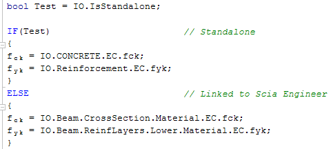
The existing statements on Lines 426 & 427 are thus replaced by the above code.
Using the IO.IsStandalone method on Line 426 it is tested if the Form runs standalone or linked with SCIA Engineer. In case this boolean is True, both the fck and fyk values are read from their respective Target IO nodes.
In case the boolean is False it means the Form is run from SCIA Engineer. In that casethe IO Structure is generated from the DataCache and thus a different structure needs to be used. The fck and fyk values are in this case read from the .emd files in the DataCache.
After making the above changes to the Form, refresh the Form by pressing the button  or the F5 key.
The entire block of code from Line 426 to 437 can be selected and its Visibility disabled so it is not shown on the output.
This concludes the first part of this step; all input variables for the Form which can be obtained from the DataCache are now properly linked to ESA.ID's. In addition the Form was modified to account for the difference in the IO Structure between a standalone run and a run when linked to SCIA Engineer.
In this example there is one result value which will be defined, the Reinforcement Area As. This variable will thus be given the ID Result.1.
In order to let the Form take into account the ID's defined in this Step refresh the form either by pressing the button or the F5 key.
This concludes the definition of the in- and output variables.