![]()
|
||
|
|
||
After setting the ESA.ID's and optionally inputting Member data the 'Check Header' can be defined.
Switch to the tab 'Header' to define the Check Header.
The Check Header is divided into two separate parts: the first part allows the definition of the check name, specify for which material and codes it is valid etc. The second part shows the previously defined Result values and provides output settings for these values.
When initially opening the 'Header' tab the following data is shown by default:
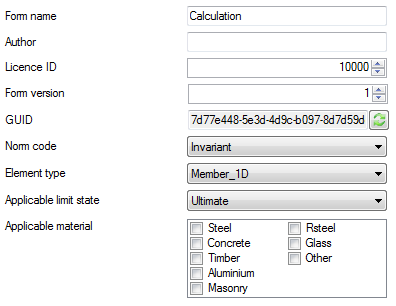
The Form name shows the name by which this check will be shown within the Tree of SCIA Engineer.
For this example, the name is changed to Bending Check.
The Author field is used to specify the name of the author of this Form. For this example the field is left blank.
The License ID is used to set the license number which is needed to use this Form. For this example the License is left on the default public license number 10000.
The Form version can be used by the author to specify the version of the Form. This is convenient when making updates to the Form for example, so the version can be increased accordingly. In this example the version is kept on 1.
The GUID field shows the Globally Unique IDentifier of the Form. The GUID is a unique reference number which is used to differentiate between Forms. No two Forms can have the same GUID. The  button can be used to generate a new GUID if needed. For this example the default generated GUID is kept.
The Norm code field is used to indicate the default code to which this Check applies. Typically Checks are code dependent and thus have one specific code which can be indicated. In case the code selection is of no importance for a Form this field can be set to 'Invariant'. Within SCIA Engineer, a Check will only be visible in case the specified code is selected. For this example the code is set to EuroCode.
Since the EuroCode in turn has multiple National Annexes an additional selection appears for the National Annex. In this example no selection of the National Annex is made.
The Element type is used to indicate the type of element to which this check applies. A check can either be a 0D Check (a check on nodal elements like a Punching Check, Pad Foundation Check, Connection Check, ...), a 1D Check (a check on beam/column elements like a Steel Beam Check, Concrete Column Check, Timber Girder Check, ...) or a 2D Check (a check on slab/wall elements like a Concrete Slab Check, Timber Wall Check, ...). Since this example concerns a Steel Bending Check for beam elements the type is left on the default Member 1D.
The Applicable limit state field is used to filter the type of results which will be available for this check. Within SCIA Engineer, the type of combinations in the Check service are filtered based on this setting. When this setting is set to 'Ultimate' only Ultimate combinations are visible in the Check Service. When this setting is set to 'Serviceability' only Serviceability combinations are visible in the Check Service. Using 'Both' any type of combination is shown. For this example, since it concerns a Steel Bending Check the type is left on the default Ultimate.
The Applicable material setting is used to indicate the material(s) to which this check applies. Only elements with all of the selected materials will be used for the check. Since this example concerns a Steel Check only the Steel material is activated.
In case for example a Composite Steel-Concrete check is defined, both the Steel and Concrete materials should be activated. In that case only those members which have cross-sections with BOTH Steel & Concrete will be used for the check.
After the above modifications the Check Header definition looks as follows:
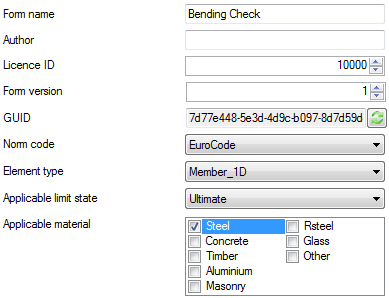
As a summary of the above settings:
- The Check will be visible only in EuroCode
- The Check service will show only Ultimate combinations
- The Check is executed only on 1D Members which have cross-sections with material Steel
The bottom part of the Check Header definition shows a grid which automatically lists all variables that were defined as output results in Step 2.2.

In this example the UCCombined was set as Result.1 so this is the only variable shown here.
For each output variable different settings can now be defined which are used by the Brief output in SCIA Engineer.
The ESA unit is used to link the variable to a specific unit setting of SCIA Engineer. This way, when unit settings within SCIA Engineer are modified, the Brief output of the Open Check is modified accordingly. A typical example is the unit change of [m] to [mm] or the change of the number of decimal places.
In this example, the UCCombined variable concerns a unity check. The unit is therefore set to Others - Unity Check [-].
Note that the structure of the unit setting corresponds to the Units within SCIA Engineer: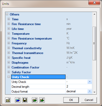
The Extreme setting is used to indicate what the extreme is for this variable
Since in this example the output variable concerns a unity check the extreme is left on the default Maximum.
The Hide zero values checkbox is used to indicate that this variable will not be printed in the Brief output in case it is zero for all sections in the output table. This can be used when multiple output values are presented of which several are zero in specific cases, in order not to overload the output with many zeros. In this example the checkbox will remain unchecked.
Within SCIA Engineer, Check results are also graphically shown on the screen. The following picture shows an example of such a graphical result:
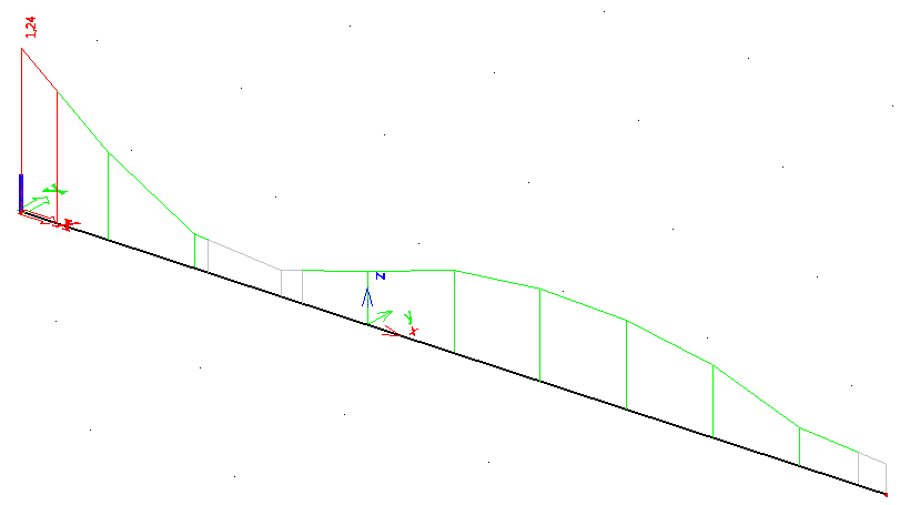
As the picture shows, for a typical check the result is drawn in the Positive direction of the z-axis of the beam. This can be defined in the Check Header using the Draw direction and Reverse axis settings. With a Draw Direction of Z the result will be plotted in the positive Z-direction. In case the Reverse axis checkbox is checked a positive result will be plotted in the negative Z-direction.
For this example, since it concerns a standard check, the defaults are kept so the Draw Direction is left on Z and the Reverse axis checkbox remains unchecked.
The above picture also shows that the color of the graphical result changes based on its value. Typically within SCIA Engineer, a unity check below a limit of 0,25 is insignificant and shown in grey. Any unity check above 1,00 is shown in red and anything in between is shown in green.
Within the Check Header these limits can be set in the Drawing limit - minimum and Drawing limit - maximum fields. In this example the defaults of 0.25 and 1.00 are kept.
The final column Units shows the unit of the output variable which was inputted for it within the Form. Since in this Form no unit was inputted for UCCombined nothing is shown here.
After the above modifications the second part of the Check Header definition looks as follows:

This concludes the definition of the Check Header; all required inputs have now been made.