![]()
|
||
|
|
||
The Check for Combined bending and Axial Compression is executed according to EN 1993-1-1 art. 6.3.3 and Annexes A & B.
For prismatic members the value My,Ed is the maximum value of the bending moment around the strong axis in the member. The value Mz,Ed is the maximum value of the bending moment around the weak axis in the member.
For non-prismatic sections, the values My,Ed and Mz,Ed are the concurrent bending moments for each intermediary section.
For non-prismatic members the maximal moments are still used in the determination of the moment factors Cmi,0 when using the General formula.
For both Interaction Methods, in case Torsional Buckling is limiting (χTF < χz) the value for χz is replaced by the value of χTF and used in all formulas.
For Interaction Method 1 there is a discrepancy in the use of Ncr,T or Ncr,TF:
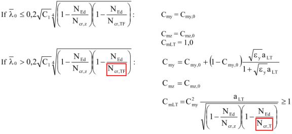
Within ECCS 119 Ref[9] as well as the ECCS Design manual for EN 1993-1-1 all formulas are written using Ncr,T. Therefore also within SCIA Engineer Ncr,T is used.
Interaction Method 1 uses several 2nd order terms which relate to Ncr,y ; Ncr,z ; Ncr,T.
For example:
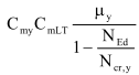
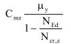
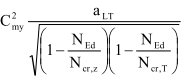
In case NEd exceeds any of those critical forces this would lead to an undetermined result (more specifically the member already fails in buckling so technically there is no use in verifying the combined check.)
In such a case, thus when NEd exceeds any of the critical forces, the combined check itself is not executed. Instead the limit forces are printed to indicate which one is exceeded and the check is set to 999.
Interaction Method 2 makes a distinction between members susceptible and not-susceptible to torsional deformations. Within SCIA Engineer this distinction is done as follows:
Doubly symmetric I sections which have a reduction factor for Lateral Torsional Buckling χLT equal to 1,00 are classified as non-susceptible to torsional deformations.
Circular hollow sections are classified as non-susceptible to torsional deformations.
Rectangular hollow sections are classified as non-susceptible to torsional deformations if the following condition is fulfilled (Ref.[9] pp.119).

| h |
Height of RHS section |
|
b |
Width of RHS section |
|
|
Relative slenderness for weak axis flexural buckling |
Interaction Method 2 uses specific formulas which subtract a constant value from the relative slenderness:
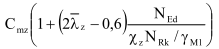
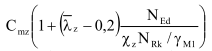
In these formulas, in case  < 0 or
  < 0 this part is set to 0.
