![]()
|
||
|
|
||
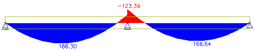
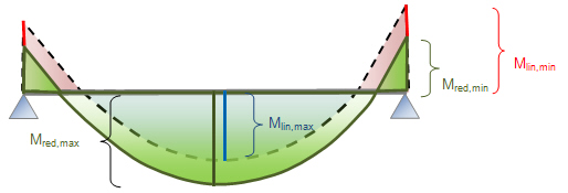
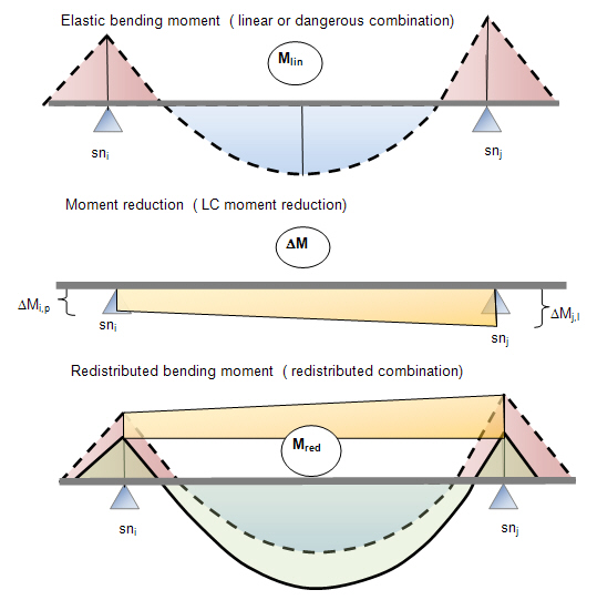
The target of this project is the calculation and check of the redistribution of bending moment My (moment around the local y-axis). Moment Mz (moment around the local z-axis) is not redistributed. The redistribution means decreasing bending moments above supports and increasing bending moments in mid-spans where distribution of moments remains in equilibrium with the applied loads.
The user can select four methods for the calculation of redistributed bending moment My:
· method according to EN 1992-1-1, clause 5.5,
· moment resistance (redistributed bending moment = moment of resistance),
· user method.
After the calculation of redistributed bending moment according to the above-mentioned methods, the user can check the value of redistributed bending moment according to EN 1992-1-1, clause 5.5(4) or 5.6.2(2). The moment can be redistributed, only if:
· a new type of member - continuous beam - is defined,
· additional data for redistribution are defined on continuous beam,
· a combination for redistribution is prepared.
The following steps for the calculation and check of redistributed bending moment have to be performed:
· Definition of new type of member - continuous beam (chapter 2)
· Selection of combination or construction stages for which redistribution will be calculated (chapter 3)
· Definition or change of input parameters in concrete setup (chapter 4)
· Definition of additional data for redistribution on continuous beam (type of method, selection of support...), chapter 5
· Calculation of redistributed bending moment for selected member and selected method (chapter 7)
· Check of redistribution bending moment in ULS checks (chapter 8)
Limitations:
Supported direction: only bending moment My (around the local y-axis)
Supported code: only EN 1992-1-1
Supported member: straight continuous beam
Supported cross-sections: all cross-sections
Bending moment can be redistributed only if continuous beam is defined. Continuous beam can be defined via item Continuous beam (tree Structure > Model data).
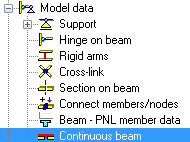
After clicking on this item the user selects the type of continuous beam:
· standard – only one option is available.
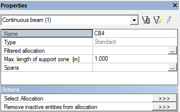
Then the user allocates the existing 1D members (by selection in graphical window) to continuous beam. The allocation of 1D members can be changed in the properties of Continuous beam via action buttons Select Allocation and Remove inactive entities from allocation.
Note:
· the continuous beam cannot be copied,
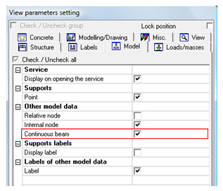
· graphical presentation and label for continuous beam can be set in dialog View parameters setting > Model > Other model data > Continuous beam.
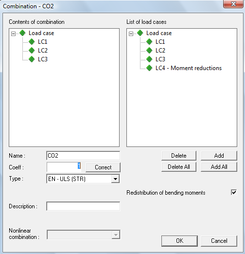
The user has to define for which combination or construction stages the redistribution should be calculated.
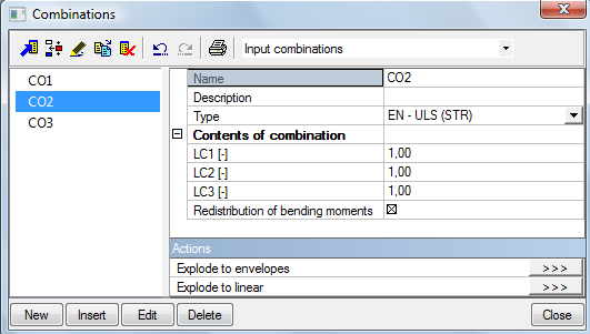
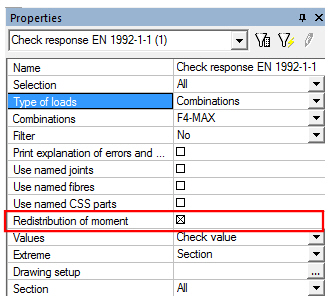
There is a new check box Redistribution of bending moments in the manager of combinations and in the dialog for editing of combination. This check box is active only for ULS combination and in case that:
· concrete material is defined in project,
· code EN 1992-1-1 is selected,
· continuous beam is defined in project.
The check box Redistribution of bending moments can be parameterized via parameter Boolean.
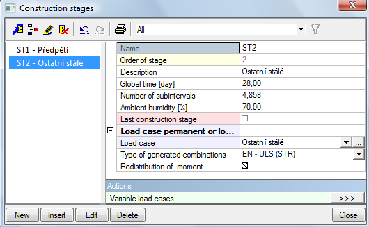
There is a new check box Redistribution of moment in properties of each construction stage. If this check box is ON, then:
· the redistributed moment will be calculated for all ULS combinations from the selected construction stage (the check box Redistribution of bending moment in properties of each ULS combination will be ON)
· supports for selected construction stage can be taken into account for redistribution.
The check box Redistribution of moment can be parameterized via parameter Boolean.
A new load case is generated and added to each combination with switching ON check box Redistribution of bending moment. This load case contains moment reduction in each result-section. Using one of the methods described below, the program calculates moment reduction above support. For the calculation of redistributed bending moments in all sections, the program uses the following procedure:
· moment reductions are recalculated in sections (a linear distribution is assumed along the length of span),
· loop for all sections in span: run cross-section solver, calculate stress, integrate forces in phases of cross-sections and the tendons,
· test the material of beams (only concrete + internal tendons in cross-sections can be calculated),
· E modulus increase over time (ageing, E modulus changes, …) is respected in calculations of forces in phases of cross-sections.
· fill in new LC by moment reduction (forces in phases of cross-sections and tendons).
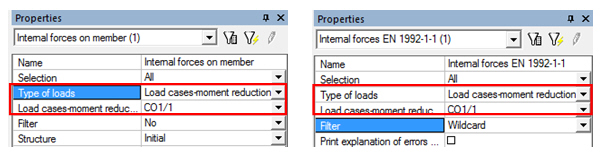
The load case with moment reduction can be presented in the services Internal forces on beam (tree Results > Beams) and Internal forces (tree Concrete Advanced > 1D member), where a new item Load cases - moment reduction is available in combo box Type of loads.
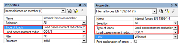
For Type of loads = Load cases - moment reduction a new combo box Load cases - moment reduction is active with the list of all load cases with moment reduction for all combinations for which Redistribution of bending moment is ON. The name of load case is derived from the name of the source redistributed combination, for example name of LC for combination F1-MAX is F1-MAX/1. The number behind the name of the combination means the number of the load case, because for envelope combination several load cases with moment reduction can be generated.
Basic principles for the generation of redistributed combination are:
· The redistributed combination can be created only for ULS combination depending on the type of calculation (analysis):
· for TDA and Construction stages analysis the combinations are generated automatically .The check box Redistribution of bending moment is ON for all ULS combinations in construction/serviceability stage in which the check box Redistribution of moment is on.
· for other type of analysis the check box Redistribution of bending moment has to be switched ON directly by the user in the dialog for the definition of combination.
· for linear combination only one load case with moment reduction is generated
· for envelope combination the following procedure is used
o the envelope combination is exploded to linear combinations in the background,
o for the selected member (only a member with redistribution data defined) and envelope combination the dangerous combinations from linear combinations are created,
o for each dangerous combination a new load case with moment reduction is created and filled in,
o the new created load cases are stored.
· the envelope combination is found from all dangerous combinations with load case moment reduction directly in the current result/concrete service
· the contents of the redistributed combination can be presented only using the Combination key
· redistributed combination is taken into account if check box Redistribution of moment in selected service (type of check) is ON
The new parameters influencing the calculation and check of the redistribution of bending moment are in:
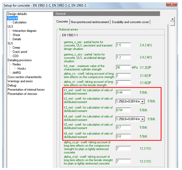
· Concrete setup > General > National annex
· Concrete setup > General > Calculation > tab-sheet Beams.
There are parameters for calculation of value d according to EN 1992-1-1, clause 5.5.4 in national annex. The value d is used for calculation of redistributed bending moment according to EN 1992-1-1 and check of redistributed bending moment according to chapter 5.5 (4).
There are parameters for the check of compression member and for selection method which is used for the check of redistribution of bending moment My.
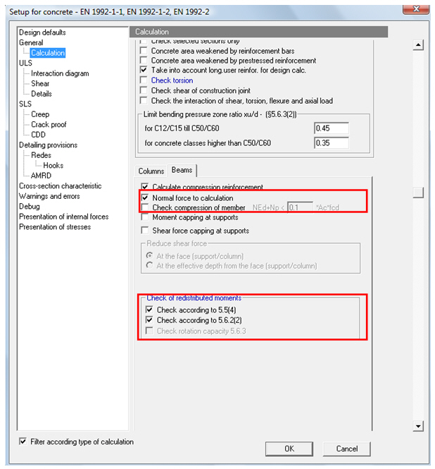
· check box Normal force to calculation
o if this check box is ON, then normal forces in beam is taken into account for the design of reinforcement, otherwise the beam is designed for the pure bending moment. This check has no influence on checks of the member. This parameter is code independent.
o default value is ON
· check boxCheck compression of member
o is active only if check box Normal force to calculation is ON
o is code independent and is used for the definition of member predominantly subject to flexure or compression.
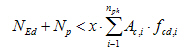
o if check box is ON then program checks the formula
§ in design reinforcement (service Design As)
§ in calculation of redistributed bending moment according to EN 1992-1-1
§ in check of redistribution according to chapter 5.5(4) (services for ULS checks, value Redistribution check)
where
|
NEd |
is normal force caused by external load |
|
Np |
|
|
x |
is relative number sets in Concrete setup, default value is 0,1 |
|
nph |
is number of phases of cross-section |
|
Ac,i |
is area of concrete of i- th phase of cross-section |
|
fcd,i |
is design value of concrete compressive strength of i- th phase of cross-section |
Design of reinforcement:
· if formula is satisfied, then program gives warning 60 (The member is not considered to be in compression) and calculation is OK
· if formula is not satisfied, then program gives warning 61 (The member is considered to be in compression) and calculation is not ok and the beam should be calculated as a column. The user must switch the type of member to column manually
Calculation of redistributed bending moment according to EN 1992-1-1:
· if formula is satisfied, then redistributed moment may be calculated
· if formula is not satisfied, then program gives error 851 (The member is not predominantly subject to flexure) and redistributed bending moment is not calculated
Check of redistribution according to chapter 5.5(4):
· if formula is satisfied, then check is OK
· if formula is not satisfied, then program gives error 851 (The member is not predominantly subject to flexure) and check is not ok
o if check box is OFF, the previous formula is checked only :
· in calculation of redistributed bending moment according to EN 1992-1-1
· in check of redistribution according to chapter 5.5(4),
because only member predominantly subject to flexure can be used in these cases.
· group Check of redistributed moments
o user can select type of method for check of redistributed moments
o two methods are supported
§ Check according to 5.5(4) - is method in EN 1992-1-1, clause 5.5 (4)
§ Check according to 5.6.2(2) - is method in EN 1992-1-1, clause 5.6.2(2)
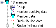
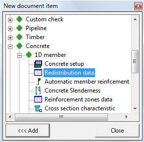
Calculation and check of redistributed moment is not possible without redistribution data, because supports and method for calculation have to be selected. Additional data for redistribution (RM data) can be input via item Redistribution data in Concrete Advanced tree > 1D member. The item is active only, if:
· code EN is selected in Project > Basic data
· concrete material is selected in Project > Basic data
· one or more continuous beams are defined in the project
After clicking on item Redistribution data, the user has to select one Continuous beam and method and supports for the calculation in dialog Redistribution moment.
Note:
· The redistribution data cannot be input to a continuous beam if the graphical presentation of continuous beam is OFF. This presentation can be set ON via View parameters setting > Model > Other model data > Continuous beam
· Only input parameter for bending moment My and for supports in direction of z-axis of LCS can be set
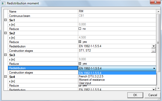
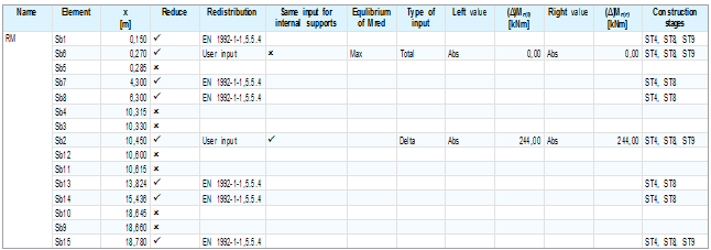
There is a list of all supports in the direction of the local z-axis (name of supports) for all construction stages in the dialog. All types of support are supported (standard supports, columns, crossing of member). Each support has the following properties:
· x [m]
o non editable value, the position of the support on the continuous beam is presented
· Reduce
o if check box is ON, the moment M above this support is redistributed,
o default value is ON
o the value can be parameterized using a Boolean parameter
· Redistribution
o combo box for selection of the type of method for the calculation of redistributed bending moment, user can select these methods:
§ EN 1992-1-1,5.5(4), default method
§ Moment of resistance
§ User input
o is active only if Reduce = ON
· Construction stages
o the supports can be defined in more construction stages and this property allow the user to select for which construction stages the moment above support will be redistributed
o is active if construction stages are defined and the check box Redistribution moment is ON for one construction stage, see chapter 3.2.
o the list of construction stages for which the moment above support will be redistributed. Only construction stages with Redistribution moment = On are listed.
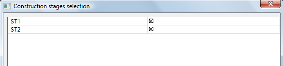
o the
list of construction stages can be edited via button  . The user can select construction
stages for which the moment above support will be redistributed. Only
construction stages with Redistribution moment = On are listed
in the dialog Construction stages selection.
. The user can select construction
stages for which the moment above support will be redistributed. Only
construction stages with Redistribution moment = On are listed
in the dialog Construction stages selection.
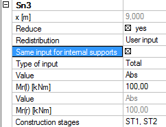
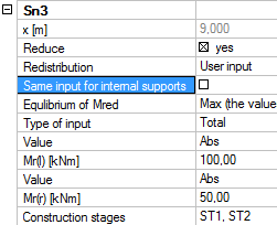
There are additional properties for user input (redistribution = User input)
· Same input of internal support
o is active only for internal support
o if the check box is OFF, then input values for left and right side of the support can be different.
o if check box is ON, then input values for both side of support are same
o the value can be parameterized via parameter Boolean
|
Same input of internal support = ON |
Same input of internal support = OFF |
|
|
|
· Equilibrium of Mred
o is active only for an internal support and if Same input of internal support is OFF
o combo box for selection of the method for equilibrium of redistributed moment above internal support. Three possibilities are supported:
§ None (defualt value), the redistributed bending moment on the left and right side of the support can be different
§ Min, the redistributed bending moment on the left and right side of the support are the same, minimum from both
§ Max, the redistributed bending moment on the left and right side of the support are the same, maximum from both
|
Equlibrium of Mred |
None |
|
|
Min |
|
|
|
Max |
|
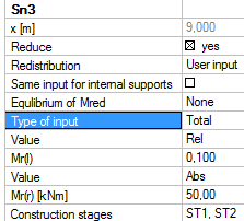
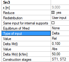
· Type of input
o combo box for selection of the type of input, two types are supported
§ Delta ,the user inputs the value ofD M (moment reduction) which is subtracted from elastic bending moment
§ Total (defualt), the user inputs directly the value of redistributed moment above support
|
Type of input = Total |
Type of input = Delta |
|
|
|
· Value
o different type can be set for both sides of internal supports
o only value for bending moment My (around y-axis of LCS) can be input
o combo box for selection of the type of value with two items.
§ Abs (default) – the value is input as real value and the values Mr(l), delta Mr(l), Mr(r), delta Mr(r) can be parametrized via parameter Moment
§ Rel – the relative value is input and the values Mr(l), delta Mr(l), Mr(r), delta Mr(r) can be parametrized via parameter Relative.
· Mr(l) or delta Mr(l)
o edit box for inputting the value on the left side of the support
o is inactive for support in the beginning of a continuous beam
o type of the value depends on properties Type of input and Value
§ Type of input = Total and Value = Abs, user inputs directly the absolute value of redistributed moment (Mr(l) ). The final value of redistributed moment is the same as the input value. The negative value should be input.
§ Type of input = Total and Value = Rel, user inputs the relative value of redistributed moment (Mr(l) ) with limitations from 0 to 1. The final value of redistributed moment depends on the value of elastic bending moment.
§ Type of input = Delta and Value = Abs, user inputs the absolute value of moment reduction (deltaMr(l)) which is subtracted from the elastic bending moment. It means that the final value of redistributed moment depends on the value of the elastic bending moment. The positive value should be input.
§ Type of input = Delta and Value = Rel, user inputs the relative value of moment reduction (deltaMr(l)). Moment reduction depends on the value of elastic bending moment .Final value of redistributed moment is calculated by subtracting the value of moment reduction from the elastic bending moment.
· Mr(r) or delta Mr(r)
o edit box for input of the value on the right side of the support
o is inactive for support at the end of continuous beam and for internal support if check box Same input of internal support is ON
o the type of the value depends on properties Type of input and Value
§ Type of input = Total and Value = Abs, the user inputs directly the absolute value of redistributed moment (Mr(r)). The final value of redistributed moment is the same as the input value. The negative value should by input.
§ Type of input = Total and Value = Rel, the user inputs the relative value of redistributed moment (Mr(r)) with limitations from 0 to 1. The final value of redistributed moment depends on the value of elastic bending moment.
§ Type of input = Delta and Value = Abs, the user inputs the absolute value of moment reduction (deltaMr(r)) which is subtracted from the elastic bending moment. It means that the final value of redistributed moment depends on the value of elastic bending moment. The positive value should by input.
§ Type of input = Delta and Value = Rel, the user inputs the relative value of moment reduction (deltaMr(r)). Moment reduction depends on the value of elastic bending moment. The final value of redistributed moment is calculated by subtracting the value of moment reduction from the elastic bending moment.
The input values of RM data can be presented in numerical output in the Document via item Redistribution data.
All properties of redistribution data are presented in default table. The input values can be changed directly in the Document (double click on the value) or via XML
The possibility of calculation and check of redistributed bending moment produced some changes in several services in comparison with previous versions of SCIA Engineer:
· new check box Redistribution of moment
o is in following services
§ Internal forces on beam ( tree Results > Beams )
§ Reinforcement design ( tree Concrete Advanced > 1D member > Automatic member reinforcement design )
§ Cross-section characteristics ( tree Concrete Advanced > 1D member )
§ Internal forces ( tree Concrete Advanced > 1D member )
§ Design As ( tree Concrete Advanced > 1D member > Member design )
§ Design of non-prestressed reinforcement in prestressed css ( tree Concrete Advanced > 1D member > Member design )
§ Check response ( tree Concrete Advanced > 1D member > Member check > Check on non-prestressed concrete)
§ Check capacity ( tree Concrete Advanced > 1D member > Member check > Check on non-prestressed concrete)
§ Check response ( tree Concrete Advanced > 1D member > Member check > Check on -prestressed concrete)
§ Check capacity ( tree Concrete Advanced > 1D member > Member check > Check on prestressed concrete)
§ Allowable stress of concrete ( tree Concrete Advanced > 1D member > Member check > Check on prestressed concrete)
§ Allowable stress of concrete ( tree Concrete Advanced > 1D member > Member check > Check on prestressed concrete)
§ Allowable principal stresses
o is active only for
§ ULS combination for which Redistribution of bending moment is ON
§ Class with one or more ULS combination for which Redistribution of bending moment isON, see chapter3
o if it is ON, the redistributed bending moment (with LC moment reduction) is taken into account, else elastic bending moment (without LC moment reduction) is taken into account
· new type of loads Load cases - moment reductions
o is in following services
§ Internal forces on beam ( tree Results > Beams )
§ Internal forces ( tree Concrete Advanced > 1D member )
o is active if one or more combinations are redistributed (check box Redistribution of bending moment in properties of combination is ON), see chapter 3
o if this type of load is selected, then the new combo box Load cases - moment reduction is active with the list of all load cases with moment reduction for all combinations for which Redistribution of bending moment is ON. The name of load case is derived from the name of source redistributed combination.
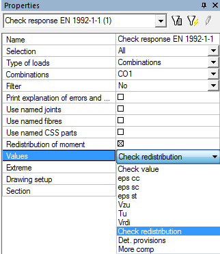
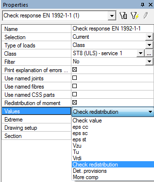
· new value Check redistribution
o is in the following services
§ Check response ( tree Concrete Advanced > 1D member > Member check > Check on non-prestressed concrete)
§ Check capacity ( tree Concrete Advanced > 1D member > Member check > Check on non-prestressed concrete)
§ Check response ( tree Concrete Advanced > 1D member > Member check > Check on -prestressed concrete)
§ Check capacity ( tree Concrete Advanced > 1D member > Member check > Check on prestressed concrete)
o is active only if check box Redistribution of moment is ON
o if it is ON or selected, the value of redistributed bending moment is checked according to the settings in concrete setup (Concrete setup > General > Calculation > tab-sheet Beams > group Check of redistributed moments )
The calculation of redistributed bending moment around the local y-axis of the member runs immediately after the linear calculation (FEM analysis) where the following inputs are set:
· definition of combination and construction stages, chapter 3
· redistribution data , chapter 5
· reinforcement
o non-prestressed real user reinforcement (REDES bars or free bars)
o prestressed reinforcement (tendon or strands)
After changing the input data above, the results are deleted and calculation has to be run again. The redistributed bending moments are taken into account in services for evaluation of results and checks only if check box Redistribution of moment is ON.
Procedure for calculation:
· two end moment reductions are calculated in each span according to method below ( one moment reduction above external support, two moments above internal support - on the left and right side)
· moment reductions are recalculated into sections along the span (linear distribution is assumed along the length of the span)
· loop for all sections in span with running cross-section solver for moment reduction where
o stress is calculated,
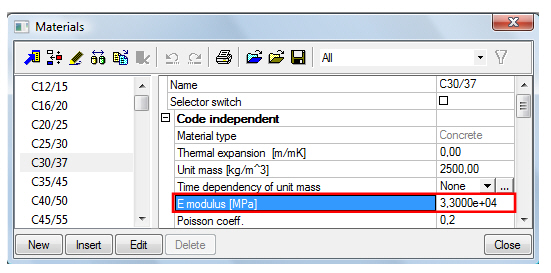
o integration of forces in phases of cross-sections and tendons is done respecting the increase of E modulus over time (ageing, E modulus changes, …),
· the results (forces in phases of cross-sections and the tendons) are filled in into the new load case - moment reduction,
· new load case - moment reduction is added to the redistributed combination (check box Redistribution of bending moment in properties of combination is ON) similarly as permanent load case, see chapter 3.3
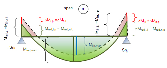
|
i, j |
is number of support |
|
n |
is number of the span of continuous beam |
|
Mlin,i,p |
is elastic bending moment above i-support on the right side |
|
Mlin,j,l |
is elastic bending moment above j-support on the left side |
|
Mlin,n,l |
is elastic bending moment above left support of the span n |
|
Mlin,n,p |
is elastic bending moment above right support of the span n |
|
Mred,i,p |
is redistributed bending moment above i-support on the right side |
|
Mred,j,l |
is redistributed bending moment above j-support on the left side |
|
Mred,n,l |
is redistributed bending moment above left support of the span n |
|
Mred,n,p |
is redistributed bending moment above right support of the span n |
|
ΔMi,p |
is moment reduction above i-support on the right side |
|
ΔMj,l |
is moment reduction above j-support on the left side |
|
ΔMn,l |
is moment reduction above left support of the span n |
|
ΔMn,p |
is moment reduction above left support of the span n |
Note:
· The value of redistributed bending moment and moment reduction are input to the left or right side of support, and not to the left/right support of the span
· The moment Mz (around the local z-axis of the member is not redistributed)
Four types of method for calculation of two ends moment reduction in span are supported:
· EN 1992-1-1,5.5(4), default method
· Moment of resistance
· User input
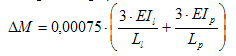
It is linear elastic analysis with limited redistribution calculated according to EN 1992-1-1, clause 5.5. The moment reduction above support is calculated according to formula

and it follows that redistributed bending moment is calculated from formula

where
|
ΔM |
is moment reduction above support |
|
Mlin |
is elastic bending moment from linear analysis |
|
Mred |
is redistributed bending moment |
|
δ |
is a ratio of redistributed bending moment to the elastic bending moment calculated according to formulas 5.10a and 5.10 b in EN 1992-1-1 d = max (d1; d2 ) < 1,0 d1 = k1 + k2?xu/d for fck ≤ 50 MPa = k3 + k4?xu/d for fck > 50 MPa d2 = k5 for class B or C of non prestressed reinforcement = k6 for class A of non-prestressed reinforcement and for prestressed reinforcement |
|
xu |
is the depth of neutral axis at the ULS calculated for redistributed bending moment calculated after second step of iterative calculation |
|
d |
is the effective depth of the cross-section |
|
k1 - k6 |
are parameters for calculation of value d, the values can be set in Concrete setup > General > National annex. Some of them are dependent on the value ecu2 |
|
εcu2 |
is the ultimate strain of the concrete. This value is automatically determined by the program from the properties of concrete in compression |
Limitations:
· non-prestressed user real reinforcement or prestressed reinforcement are input in continuous beam
· equilibrium for ULS was found
· ratio of the length of adjacent spans of continuous beam in the range 0.5 to 2 (program have to check the ratio of spans)
· the beam is predominantly subject to flexure, it means that above support the condition below is fulfilled, see chapter 4
· the ratio of redistributed bending moment to the elastic bending moment is lower than 1
· if the limitations are not fulfilled, then the moment is not redistributed and the program gives a warning or error
Note:
· the lowest quality of concrete of all phases of the cross-section is used for calculation of value d (values fck and ecu2) for calculation of cross-section with more phases
· the value k6 (class A) is used for calculation of value d for cross-section with only prestressed reinforcement
· the lowest quality of all reinforcement (k6 for class A) is used for calculation of value d for cross-section with different classes of reinforcement
· the depth of neutral axis at the ULS is calculated for redistributed bending moment that is calculated after second step of iterative calculation, because calculation of redistributed bending moment leads to an iterative calculation. Full iteration is not used because the calculation would take a lot of time.
For calculation of moment reduction according to French DTU clause 3.2.2.5c is used. Redistribution is estimated on the basis of a localized rotation above the support equal to 0.003 rad. The moment reduction, redistributed towards the neighbouring spans, can be calculated in the 1st approximation as:
where
|
ΔM |
is moment reduction above support |
|
EIl |
is flexural stiffness of the left span of continuous beam at the support |
|
Ll |
is length of the left span of continuous beam at the support (the value is presented in properties of continuous beam, see chapter 2) |
|
EIp |
is flexural stiffness of the right span of continuous beam at the support |
|
Lp |
is length of the right span of continuous beam at the support (the value is presented in properties of continuous beam, see chapter 2) |
For usual floor beam stiffness, this value leads generally to a moment reduction around a 10th of the elastic moment of the neighbouring spans.
Limitations:
· there are no limitations for this method
Note:
· the lowest quality of concrete of all phases of the cross-section is used for calculation (value Ec) of cross-section with more phases
· the flexural stiffness EIl is calculated on the left side of the support (just in front of the section)
· the flexural stiffness EIp is calculated on the right side of the support (just behind the section)
· the secant module of elasticity from properties of material is used for the calculation
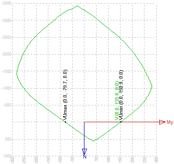
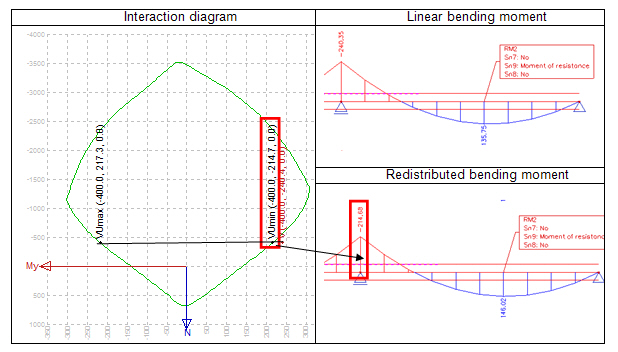
The redistributed bending moment above support equals the moment of resistance of the cross-section. Moment of resistance is determined from the interaction diagram for the method Mu (moment of resistance is calculated as an intersection of parallel line with axis of MRd crossing the point [NEd;MEd,y;MEd,z] ) and interaction diagram ). The axis MRd is resultant of vectors MRd,y and MRd,z
Note:
· The line for calculation of intersection with interaction diagram is parallel with line My in this case, because moment Mz is zero.
The redistributed bending moment and moment reduction are calculated according to procedure below
Mred = MRd,min (Vu,min) if Mlin (V) < 0 kNm
Mred = MRd,max (Vu,max) if Mlin (V) ≥ 0 kNm

where
|
ΔM |
is moment reduction above support |
|
Mlin |
is elastic bending moment from linear analysis |
|
Mred |
is redistributed bending moment |
|
MRd,min (Vu,min) |
is minimum value of moment of resistance determined from interaction diagram of the cross-section. The value in brackets is symbol used in the program |
|
MRd,max (Vu,max) |
is maximum value of moment of resistance determined from interaction diagram of the cross-section. The value in brackets is symbol used in the program |
Limitations:
· non-prestressed user real reinforcement or prestressed reinforcement are input in continuous beam
· if the limitations are not fulfilled, then the moment is not redistributed and the program gives a warning or error
The redistributed bending moment or moment reduction is directly input by the user in redistributed data, see chapter 5. The value of redistributed bending moment and moment reduction depends on properties Type of value and Value in redistribution data and they are calculated according to table below
|
Properties in redistribution data |
Formulas for calculation |
||
|
Type of input |
Value |
Redistributed moment |
Moment reduction |
|
Total |
Abs |
Mred = Input |
DM = Mlin - Input |
|
Total |
Rel |
Mred = Input?Mlin |
DM = Mlin?(1-Input) |
|
Delta |
Abs |
Mred = Mlin - Input |
DM = Input |
|
Delta |
Rel |
Mred = Mlin?(1-Input) |
DM = Mlin?Input |
where
|
ΔM |
is moment reduction above support |
|
Mlin |
is elastic bending moment from linear analysis |
|
Mred |
is redistributed bending moment |
|
Input |
is input value in properties Mr(l) or delta Mr(l) and Mr(r) or delta Mr(r) in redistribution data |
Limitations:
· there are no limitations for this method
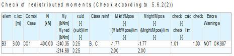
The user can check calculated redistributed bending moment My (around the local y-axis of the member) using two methods:
· Check according to 5.5(4) - is method in EN 1992-1-1, clause 5.5 (4)
· Check according to 5.6.2(2) - is method in EN 1992-1-1, clause 5.6.2 (2)
Type of the method can be set in Concrete setup > General > Calculation > tab-sheet Beams > group Check of redistributed moments (no, one or more method can be ON). The redistributed bending moment can be checked in the following services:
· Check response ( tree Concrete Advanced > 1D member > Member check > Check on non-prestressed concrete)
· Check capacity ( tree Concrete Advanced > 1D member > Member check > Check on non-prestressed concrete)
· Check response ( tree Concrete Advanced > 1D member > Member check > Check on -prestressed concrete)
· Check capacity ( tree Concrete Advanced > 1D member > Member check > Check on prestressed concrete)
For check of redistribution some conditions have to be fulfilled:
· the check box Redistribution of moment is ON
· the check boxes Check according to 5.5(4) or Check according to 5.6.2(2) are ON in Concrete setup
· value Check redistribution is ON or selected.
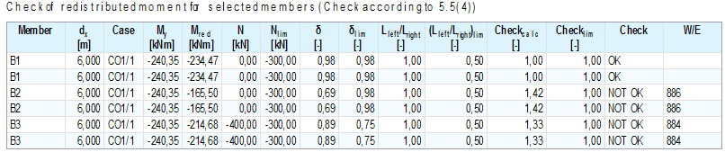
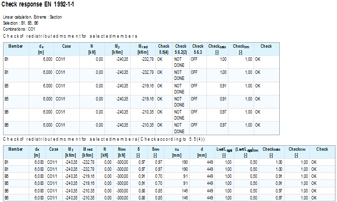
The redistributed bending moments are checked only in sections above supports. The maximum check value from all selected methods is presented graphically. In numerical output the following is presented
· Summary table - is presented always
· Table for Check according to 5.5(4) , if this method is ON in Concrete setup
· Table Check according to 5.6.2(2), if this method is ON in Concrete setup
Note:
· if redistributed bending moment in some section does not satisfy, the other check where bending moment is taken into account (check capacity, check stress, check strain....) is not done and program gives error 898 (The check of redistributed bending moment does not satisfy. Use linear internal forces only).
· if equilibrium for ULS is not found in the section above support, the check redistribution will not be done, program gives error 583 (Forces are zero or no equilibrium found ) and there is no results for this section in tables for check according to 5.5(4) and 5.6.2(2).
The check of redistribution is performed according to the diagram below
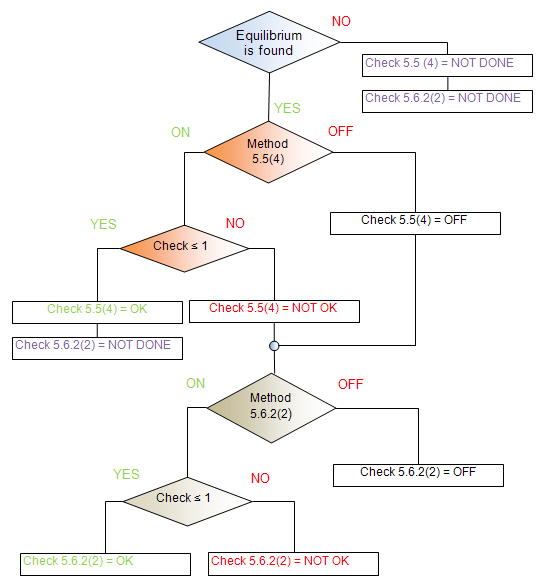
The results of all checks are presented in Summary table in the member check or in the single check
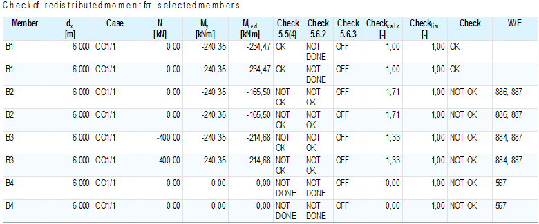
There are the following values in tables and in table composer
|
Member |
the name and number of the member |
|
dx |
position of standard result section |
|
Case |
type and name of extreme load case/combination/class |
|
N |
normal force |
|
Nlim |
limit normal force to be considered predominantly subject to flexure |
|
My |
linear bending moment before redistribution calculated for source combination of redistributed combination |
|
Mred |
redistributed bending moment calculated for redistribution combination |
|
δ |
ratio of redistributed moment to the elastic bending moment
|
|
δlim |
limit ratio of redistributed moment to the elastic bending moment calculated according to formula 5.10 |
|
Check 5.5(4) |
Check redistributed bending moment according to EN 1992-1-1, chapter 5.5(4). The result of check can be: OK - if check satisfies NOT OK - if check does not satisfy OFF - if check is OFF in Concrete setup NOT DONE - if equilibrium is not found |
|
Check 5.6.2(2) |
Check redistributed bending moment according to EN 1992-1-1, chapter 5.6.2(2). The result of check can be: OK - if check satisfies NOT OK - if check does not satisfy OFF - if check is OFF in Concrete setup NOT DONE - if check is ON in Concrete setup and check according to 5.5(4) satisfy or if equilibrium is not found |
|
Check 5.6(3) |
Check redistributed bending moment according to EN 1992-1-1, chapter 5.6(3). This check is not implemented, therefore status of this check is always OFF |
|
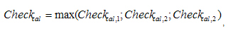
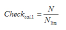
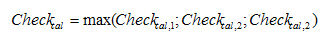
Checkcal |
The value of unit check of all partial checks |
|
Checklim |
The limit value of unit check. |
|
Check |
The results of check (OK or NOT OK) |
|
W/E |
the number of warning or error |
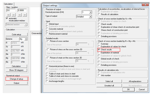
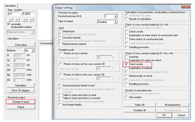
The tables for check detailing provisions are presented in the Document, if
· the check box Check results in dialog Change of setup is ON
· section above support is selected
The summary table in single check contains the following values:
This check is performed according to EN 1992-1-1, clause 5.5(4) and it contains three partial checks:
· if the member is predominantly subject to flexure
· ratio of adjacent spans
· ratio of redistributed moment to the elastic bending moment
If the check is satisfied, linear elastic analysis with limited redistribution can be used at ULS. The check satisfies only in case that all partial checks are fulfilled. The unit check is calculated as maximum value of all partial checks
If the check does not satisfy, the redistributed bending moment does not satisfy too and should be checked using plastic analysis or the linear elastic bending moment has to be used for the calculation.
The EN 1992-1-1 code does not define when the member is predominantly subject to flexure, therefore was added to the concrete setup a new check box Check of compression of member (see chapter 4) which is used for this check too.
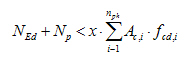
The member is predominantly subject to flexure if the condition below is fulfilled
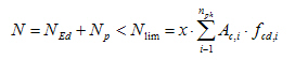
where
|
N |
is normal force caused by external load and prestressing |
|
NEd |
is normal force caused by external load |
|
Np |
is normal force caused by prestressing |
|
Nlim |
is limit normal force to predominantly subject to flexure |
|
x |
is relative number set in Concrete setup, default value is 0,1 |
|
nph |
is number of phases of cross-section |
|
Ac,i |
is area of concrete of i- th phase of cross-section |
|
fcd,i |
is design value of concrete compressive strength of i- th phase of cross-section |
The unit check is calculated as ratio of normal force caused by external load and by prestressing to limit normal force.
Note:
· this check is performed always independently on activity of check box Check of compression in Concrete setup > General > Calculation > tab-sheet beam,
· if unit check ( N/Nlim ) is greater than 1, the program gives warning 884 (The member is not predominantly subject to flexure).
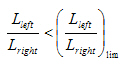
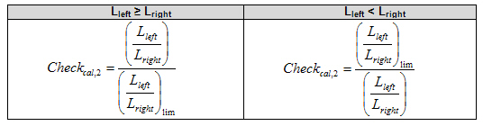
The check is performed only for the internal support of a continuous beam for which the following condition has to be satisfied
2,0 3 Lleft/Lright 3 0,5
The condition can be also written as
where
|
Lleft |
is the length of span on the left side of support |
|
Lright |
is the length of span on the right side of support |
|
Lleft/Lright |
is ratio of adjacent spans |
|
(Lleft/Lright)lim |
is limit ratio of adjacent spans if Lleft ≥ Lright , then (Lleft/Lright)lim = 2 if Lleft < Lright , then (Lleft/Lright)lim = 0,5 |
The unit check is calculated according to formulas bellow
Note:
· this check is provided only for the internal support of a continuous beam,
· if this check is not fulfilled the program gives warning 885 (Ratio of the length of adjacent spans is out of the range (0.5-2.0)).
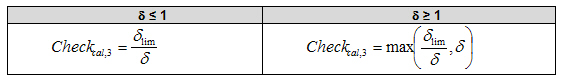
The following condition is checked in this check:

where
|
δ |
is ratio of redistributed moment to elastic bending moment
|
|
Mlin |
is elastic bending moment from linear analysis |
|
Mred |
is redistributed bending moment |
|
δlim |
is a limit ratio of redistributed bending moment to the elastic bending moment calculated according to formulas 5.10a and 5.10 b in EN 1992-1-1 dlim = max(k1+ k2×xu/d; k5) for fck ≤ 50 MPa and for class B and C of non-prestressed reinf. = max(k1+ k2×xu/d; k6) for fck≤ 50 MPa and for class A of non-prestressed reinf. and for prestressed reinforcement = max(k3+ k4×xu/d; k5) for fck > 50 MPa and for class B and C of non-prestressed reinf. = max(k3+ k4×xu/d; k6) for fck > 50 MPa and for class A of non-prestressed reinf. and for prestressed reinforcement |
|
xu |
is the depth of compression zone at the ULS calculated for redistributed bending moment |
|
d |
is the effective depth of the cross-section |
|
k1 - k6 |
are parameters for calculation of value d, the values can be set in Concrete setup > General > National annex. Some of them are dependent on the value ecu2 |
|
ecu2 |
is the ultimate strain of concrete. This value is automatically determined by the program from the properties of concrete in compression |
The unit check is calculated according formula below
Note:
· the lowest quality of concrete of all phases of cross-section is used for calculation of value dlim (values fck and ecu2) for calculation of the cross-section with more phases
· the value k6 (class A) is used for calculation of value dlim for cross-section with only prestressed reinforcement
· the lowest quality of all reinforcement (k6 for class A) is used for calculation of value dlim for cross-section with different classes of reinforcement
· the depth of neutral axis at the ULS is calculated after redistribution (for redistributed bending moment).
· if this check is not fulfilled the program gives warning 886 (Ratio of redistributed bending moment to elastic is lower than the limit value or greater than 1.0)
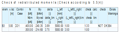
Numerical output can be presented in member check or in single check.
There are two types of table for presentation of results for check redistribution bending moment according to 5.5 (4)
· default
· detailed
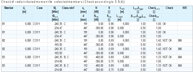
There are the following values in tables and in table composer
|
Member |
the name and number of the member |
|
dx |
position of result section |
|
Case |
type and name of extreme load case/combination/class |
|
N |
normal force |
|
Nlim |
limit normal force to be considered predominantly subject to flexure |
|
My |
linear bending moment before redistribution calculated for source combination of redistributed combination |
|
Mred |
redistributed bending moment calculated for redistribution combination |
|
δ |
ratio of redistributed moment to the elastic bending moment
|
|
δlim |
limit ratio of redistributed moment to the elastic bending moment calculated according to formula 5.10 |
|
Lleft/Lright |
ratio of adjacent spans |
|
(Lleft/Lright)lim |
limit ratio of adjacent spans |
|
Lleft |
length of span on the left side of support (effective span) |
|
Lright |
length of span on the right side of support (effective span) |
|
xu |
depth of compression zone axis after redistribution |
|
d |
effective depth of cross-section |
|
Class.reinf |
class of reinforcing steel |
|
fck |
characteristic compressive cylinder stress of concrete in the compressed zone |
|
Checkcal |
the value of unit check of all partial checks |
|
Checklim |
the limit value of unit check. |
|
Check |
the results of check (OK or NOT OK) |
|
W/E |
the number of warning or error |
Tables for check of detailing provisions are presented in the Document if:
· check box Check results in dialog Change of setup is ON
· section above support is selected
The table for check according to 5.5(4) in single check contains the following values:
It is a method of check using a plastic analysis without direct calculation of rotation capacity. Plastic analysis is an extreme case of moment redistribution, where moment is distributed in accordance with the structure's ability to resist them.
This check is performed according to EN 1992-1-1, clause 5.6.2(2) and it contains three partial checks
· check of depth of compression zone after redistribution
· check of class of reinforcement
· check of ratio of the moments at intermediate support to the moment in the span
The check satisfies only in case that all partial checks are fulfilled. The unit check is calculated as the maximum value of all partial checks
If the check does not satisfy, the redistributed bending moment does not satisfy and should be checked using plastic analysis with direct calculation of rotation capacity (EN 1992-1-1, clause 5.6.3) or linear elastic bending moment has to be used for the calculation.
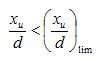
Adequate rotation capacity for plastic analysis is deemed to be achieved if depth of compression zone is restricted to depth as follows (EN 1992-1-1, clause 5.6.2(2)):
where
|
xu |
is depth of compression zone axis after redistribution |
|
d |
is effective depth of cross-section |
|
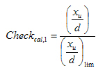
xu/d |
is calculated ratio of xu/d |
|
(xu/d)lim |
is limit ratio of xu/d (xu/d)lim = 0,25 for fck ≤ 50 MPa (strength classes ≤ C50/60) (xu/d)lim = 0,15 for fck > 50 MPa (strength classes ≥ C55/67) |
|
fck |
is characteristic compressive cylinder stress of concrete in the compressed zone |
The unit check is calculated according to formula below
Note:
· the lowest quality of concrete of all phases of cross-section is used for calculation of limit ratio xu/d for calculation of cross-section with more phases
· if this check is not fulfilled, the program gives error 887 (Depth of neutral axis after redistribution does not satisfy)
· if value xu > d, then the check is not performed (value xu/d is not calculated and appeared in numerical output ) and the program gives warning 288 (The check xu/d is not performed, because xu > d (member in compression))
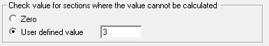
Only reinforcement with a big ductility can be used for plastic analysis, therefore class A of non-prestressed reinforcement and prestressed reinforcement cannot be used for this check due to its low ductility.
The value for unit check for class A of non-prestressed reinforcement and for only prestressed reinforcement is loaded from Concrete setup > Errors and warning > group Check value for section, where the value cannot be calculated. For other classes of reinforcement, the unit check is not calculated.
Note:
· this check is not fulfilled and program gives error 863 (Reinforcement of class A or prestressed reinforcement is not recommended for this check) if:
o only Class A of non-prestressed reinforcement is defined in the checked section,
o only prestressed reinforcement is defined in the checked section
o prestressed reinforcement and class A of non-prestressed reinforcement is defined in the checked section
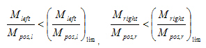
The ratio of moments at intermediate supports to those in adjacent span must lie between 0.5 and 2.0 (EN 1992-1-1, clause 5.6.2(2). It means that
where
|
Mleft |
is elastic bending moment on the left side of the support |
|
Mpos,l |
is the maximal elastic bending moment in the left span |
|
Mright |
is elastic bending moment on the right side of the support |
|
Mpos,r |
is the maximal elastic bending moment in the right span |
|
Mleft/Mpos,l |
is ratio of elastic bending moment on the left side of the support to the elastic moment in the left span |
|
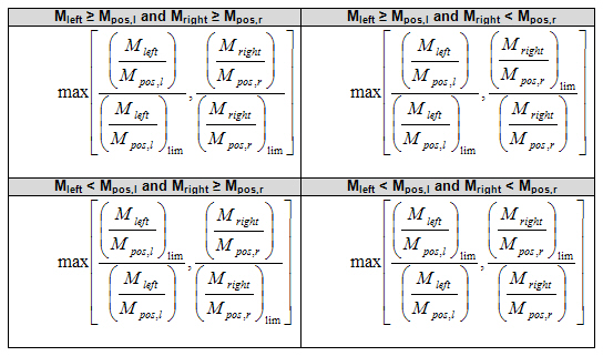
(Mleft/Mpos,l)lim |
is limit ratio of bending moment on the left if Mleft ≤ Mpos,l , then (Mleft/Mpos,l)lim = 2 if Mleft > Mpos,l, then (Mleft/Mpos,l)lim = 0,5 |
|
Mright/Mpos,r |
is ratio of elastic bending moment on the right side of the support to the elastic moment in the right span |
|
(Mright/Mpos,r)lim |
is limit ratio of bending moment on the right if Mright ≤ Mpos,r , then (Mright/Mpos,r)lim = 2 if Mlright > Mpos,r, then (Mright/Mpos,r)lim = 0,5 |
The unit check is calculated according to formulas bellow
Note:
· this check is provided for intermediate support of continuous beam, where elastic bending moment Mleft or Mright are non zero
· for outside support only one side of support is checked, if elastic bending moment above this support in non-zero
o support at the beginning of the member (right side of support is checked, if Mright 1 0)
o support at the end of the member (left side of support is checked, if Mleft 1 0)
· if unit check of this check is greater than 1, the check is not fulfilled and the program gives error 888 (Ratio of the elastic moments at the supports to elastic moment in the span is out of the range (0.5-2.0))
Numerical output can be presented in member check or in single check.
There are two types of table for presentation of results for check redistribution bending moment according to 5.5 (4)
· default
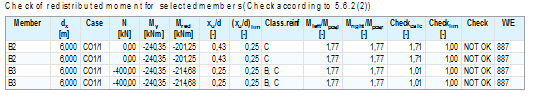
· detailed
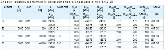
There are the following values in tables and in table composer
|
Member |
the name and number of the member |
|
dx |
position of result section |
|
Case |
type and name of extreme load case/combination/class |
|
N |
normal force |
|
My |
linear bending moment before redistribution calculated for source combination of redistributed combination |
|
Mred |
redistributed bending moment calculated for redistribution combination |
|
Mleft |
is elastic bending moment on the left side of the support |
|
Mpos,l |
is the maximal elastic bending moment in the left span |
|
Mright |
is elastic bending moment on the right side of the support |
|
Mpos,r |
is the maximal elastic bending moment in the right span |
|
Mleft/Mpos,l |
is ratio of elastic bending moment on the left side of the support to the elastic moment in the left span |
|
(Mleft/Mpos,l)lim |
is limit ratio of bending moment on the left |
|
Mright/Mpos,r |
is ratio of elastic bending moment on the right side of the support to the elastic moment in the right span |
|
(Mright/Mpos,r)lim |
is limit ratio of bending moment on the right |
|
xu |
depth of compression zone axis after redistribution |
|
d |
effective depth of cross-section |
|
xu/d |
is calculated ratio of xu/d |
|
(xu/d)lim |
is limit ratio of xu/d |
|
fck |
is characteristic compressive cylinder stress of concrete in the compressed zone |
|
Class.reinf |
class of reinforcing steel |
|
fck |
characteristic compressive cylinder stress of concrete in the compressed zone |
|
Checkcal |
The value of unit check of all partial checks |
|
Checklim |
The limit value of unit check. |
|
Check |
The results of check (OK or NOT OK) |
|
W/E |
the number of warning or error |
The tables for check of detailing provisions are presented in the Document if
· the check box Check results in dialog Change of setup is ON
· section above support is selected

The table for check according to 5.6.2(2) in single check contains the following values:
Almost all values for redistribution data for the user method can be parameterized (see chapter 5) and changed via XML. In addition, the following check boxes are parameterized
· Redistribution of bending moments in definition of combination (see chapter 3.1)
· Redistribution of moment in properties of each construction stages (see chapter 3.2)
|
REDES |
a module of SCIA Engineer for the definition and drawing of real non-prestressed reinforcement |
Six non-prestressed continuous beams with two spans, with same load, but with different number of upper bars above support and different method for redistribution of bending moment
· B1: upper bars above support =7Ø16, method according to EN 1992-1-1, 5.5(4)
· B2: upper bars above support =7Ø16, method Moment of resistance
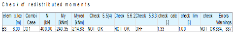
· B3: upper bars above support =7Ø16, user input, delta Mr = 30 kNm
· B4: upper bars above support =6Ø16, method according to EN 1992-1-1, 5.5(4)
· B5: upper bars above support =6Ø16, method Moment of resistance
· B6: upper bars above support =6Ø16, user input, delta Mr = 30 kNm
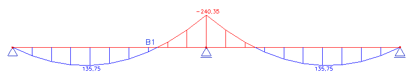
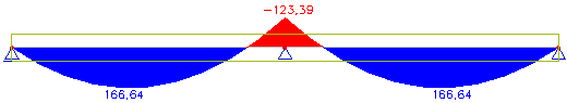
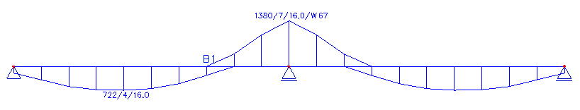
Linear internal forces along continuous beam
Required area
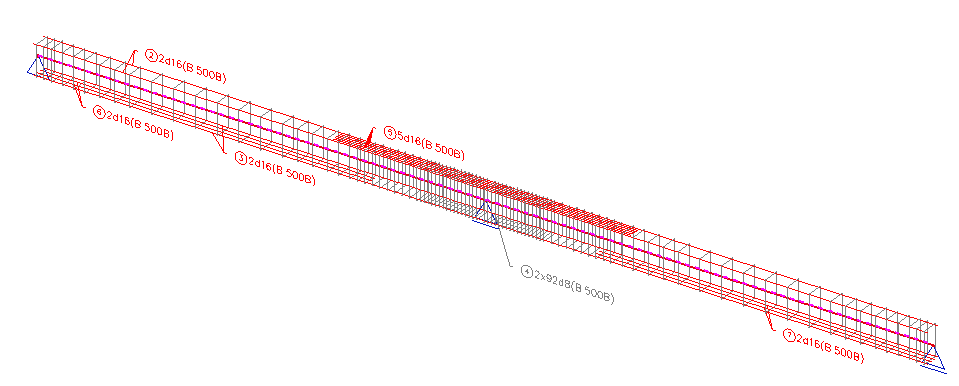
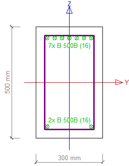
User defined reinforcement via REDES (real bars)
Check member in extreme sections for linear bending moment
|
|
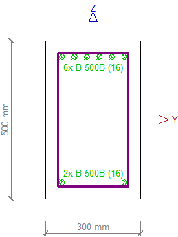
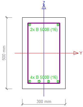
Cross-section with reinforcement |
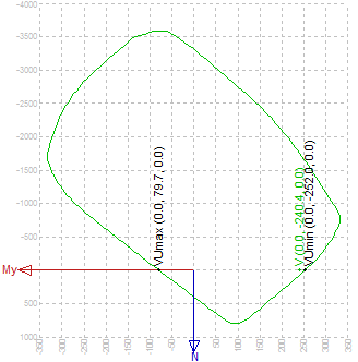
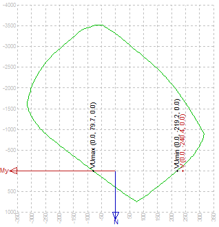
Interaction diagram |
|
Section above support for B1,B2,B3 (x =6,0 m) |
|
|
|
Section above support for B4,B5,B6 (x =6,0 m) |
|
|
|
Section at midspan (x =2,4 m and x =9,6 m) |
|
|
Section above support with 6f16 (member B4-B6) does not satisfy for linear bending moment, therefore we used functionality for redistribution.
The redistributed bending moment was calculated for three different methods and for two numbers of upper bars above support, see table below
|
The redistributed bending moment above support Mred [kNm] |
Upper reinforcement above support |
|
|
7Ø16 |
6Ø16 |
|
|
EN 1992-1-1,5.5(4) |
-232,8 (B1) |
-240,4 (B4) |
|
Moment of resistance |
-252 (B2) |
-219,6 (B5) |
|
User input (Abs,Delta Mr = 30 kNm) |
-210,4 (B3) |
-210,4 (B6) |
Note:
· the method according to EN 1992-1-1, clause 5.5(4)
o for upper reinforcement 6f16 the moment was not redistributed (is the same as the linear elastic moment) because equilibrium was not found
· the method Moment of resistance
o for upper reinforcement 7f16 redistributed bending moment is bigger than the linear elastic bending moment, therefore this redistribution is not usable
o support at the end of the member (left side of support is checked, if Mleft 1 0)
· the User method
o the redistributed bending moment is independent on reinforcement
The detailed evaluation will be done only for configurations in the table below
|
Method |
Mred [kNm] |
Upper bars |
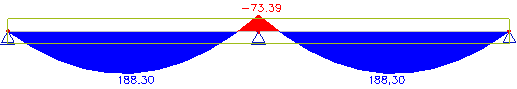
Internal forces after redistribution |
|
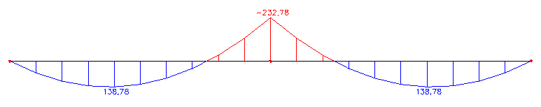
EN 1992-1-1,5.5(4) |
-232,8(B1) |
7Ø16 |
|
|
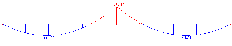
Moment of resistance |
-219,6(B5) |
6Ø16 |
|
|
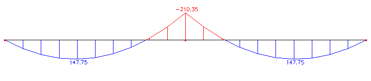
User input (Abs,Delta Mr = 30 kNm) |
-210,4(B6) |
6Ø16 |
|
Check of redistributed bending moment for member B1,B5 and B6
Check of capacity of critical section for member B1,B5 and B6
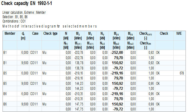
The use of redistribution bending moment decreases the bending moment above the support and it allows for decrease of the amount of reinforcement (upper bars above support) for method Moment of resistance and User input.