![]()
|
||
|
|
||
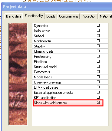
The check of voided slabs is available only for EC-EN and for such type of structure which enables using of 2D members.
It has a new functionality check box in Project setting dialog.
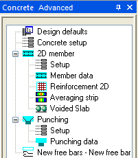
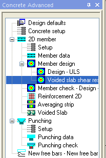
The icon for input of a new voided slab is located in service Concrete Advanced.
All 2D member components (Subregion, Opening, Internal node, Internal edge, Intersection, Cut out) can be used together with voided slabs (existing feature of the slab).
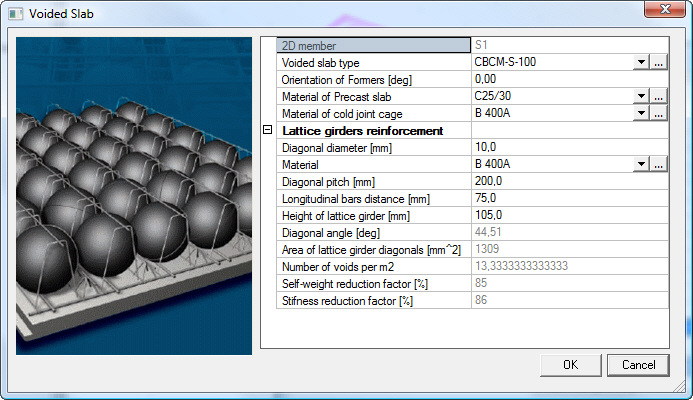
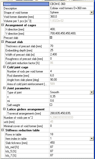
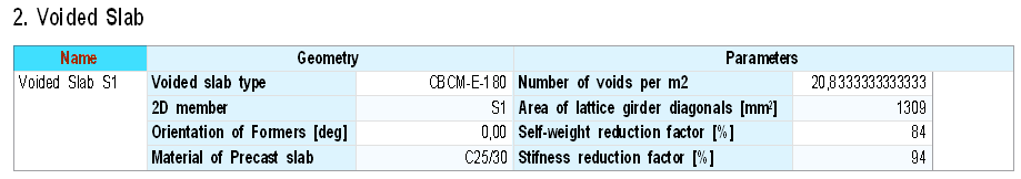
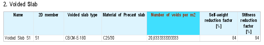
Material of the precast part of the slab and parameters of void formers are specified in the properties of member-data “voided slab”. Material of concrete poured in-situ is according to the material selected in the properties of the slab.
Slab types
Ball diameter and dimensions in group Arrangement of cages are checked against each other. The distance between balls must be greater than the ball diameter. If not it is not allowed to enter such value.
When there is a subregion in the slab containing void formers, then by default this subregion is without void formers.
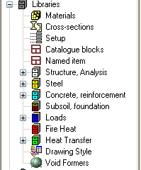
Selection of void former type is limited with respect to slab thickness via Minimal cover of void former (property of Void former type – library.)
Properties of library objects:
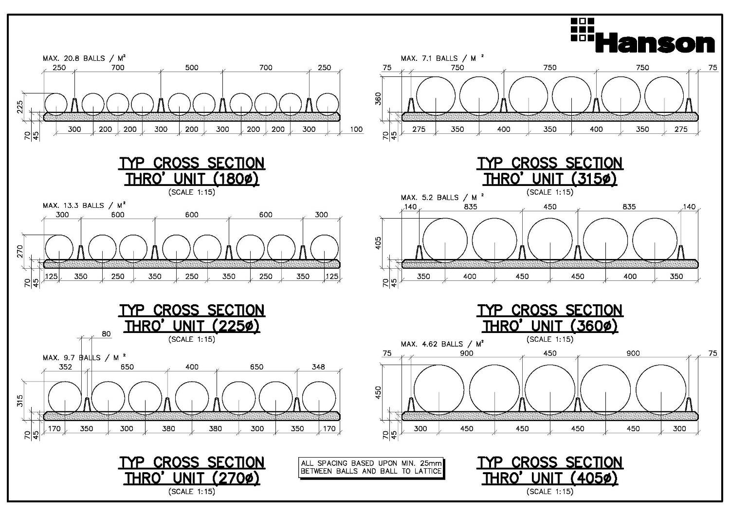
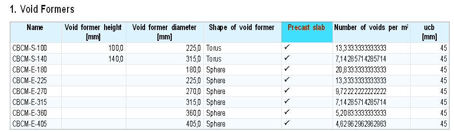
List of available diameters:
- 100 mm (torus)
- 140 mm (torus)
- 180 mm
- 225 mm
- 270 mm
- 315 mm
- 360 mm
- 405 mm
Those are default values available in the Library. User can create (add) new possible values.
The arrangement of void formers is stored as sequence of distances between balls in the X and Y direction.
Distances in the arrangement are checked and it is not possible to insert value lower that the diameter of the void former.
The volume of 1pc of void fromer is calculated automatically for spherical shapes only. For toruses it must be inserted manually. Cold joint surface reduction is calculated automatically for both shapes
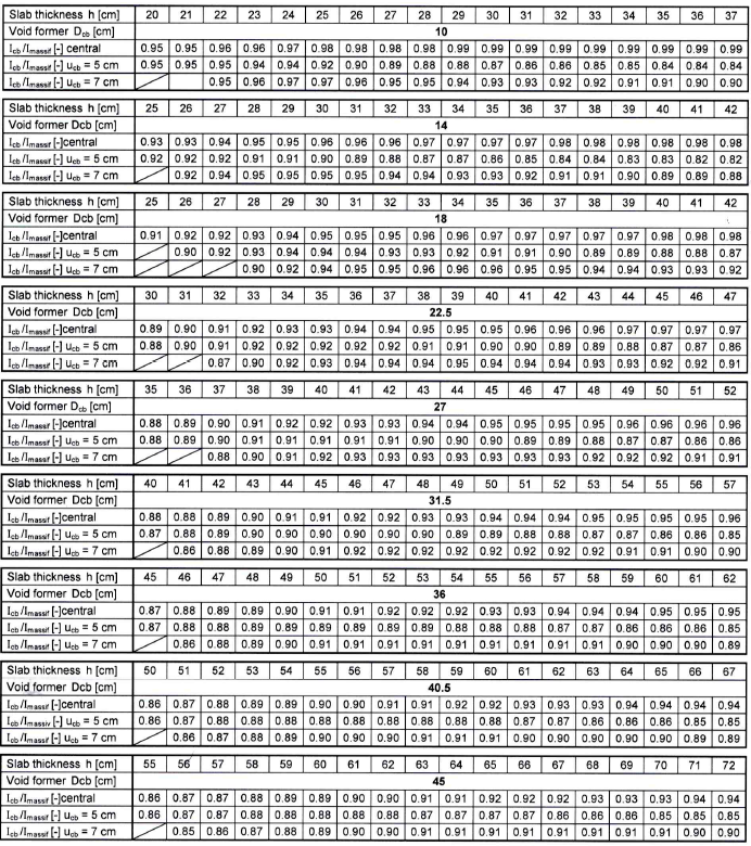
In the last group, Stiffness reduction table is stored. There are stored values for particular slab thicknesses and three positions of Void formers. Linear interpolation is used for evaluation of intermediate thicknesses and positions of void formers.
The existing pen for 2D members is used.
Labels are displayed as attributes of slabs. Labels can be switched ON/OFF in the View parameter setting. The user can display the name or the voided slab type as a label.
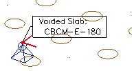
The way of displaying void-formers can be also changed in the view parameters setting. It can be switched ON/OF and user can select from three types of displaying:
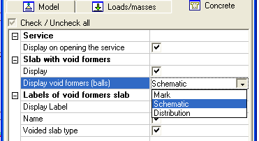
- Mark: only a small arrow is displayed (similar to concrete member data)
- Schematic: hatch pattern with circles is displayed on areas with void formers
- Distribution: the real sizes and arrangements of formers are displayed
Please note, that displaying of distribution can take remarkably longer time especially for complicated slabs.
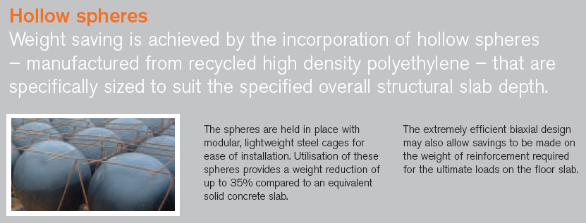
The self weight of concrete slabs with void formers is reduced by the volume of void formers. This is the primary benefit. This self weight reduction is displayed in the properties of voided slab and also is sent to the solver when generating the FE mesh.
The self weight of voided slabs is calculated with respect to the arrangement and type of void former.
The stiffness of material is reduced by a factor based on the diameter and arrangement of balls.
The shape of mesh is not influenced by the position of void formers (balls).
The mesh is influenced by sub-regions (existing feature of sub-regions).
There is nothing special about displaying standard results for voided slabs.
A new type of (check) result is developed for voided slabs:
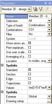
Most important for voided slabs is the value of tauD/0,6*tauR1. This is the check of shear capacity of a slab with void formers.
This shear capacity check has Action buttons which can launch automatic generation of subregions.
Values of this new shear capacity check are displayed only on areas with void formers.
Automatic creation of sub-regions is launched through the action button in the properties of the new shear stress capacity check.
The user can select one of two possible sub-region shapes:
o circle (the smallest possible) around area with exceed shear capacity)
o rectangle (bounding box around area with exceed shear capacity)
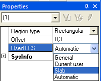
When creating rectangular sub-regions, the user can select from 4 available types of sub-region orientation:
- General: GCS
- Current user current UCS specified by user
- Slab: LCS of the parent slab
- Automatic: automatically search for orientation to get the smallest possible rectangle
Value Offset means THE distance between the isoline with value 1 and the sub-region edge.
The preview of sub-regions is available during changing of properties.
Sub-regions are created only on slabs where the results are displayed (property Section).
Manual creation of sub-regions is launched through action button in the properties of the new shear stress capacity check. It enables the user to create multiple subregions manually. The existing results are lost after finishing of insertion.
New OTXs for Voided Slab (member data) are available:
- Detailed
- Brief
- Default
- Detailed
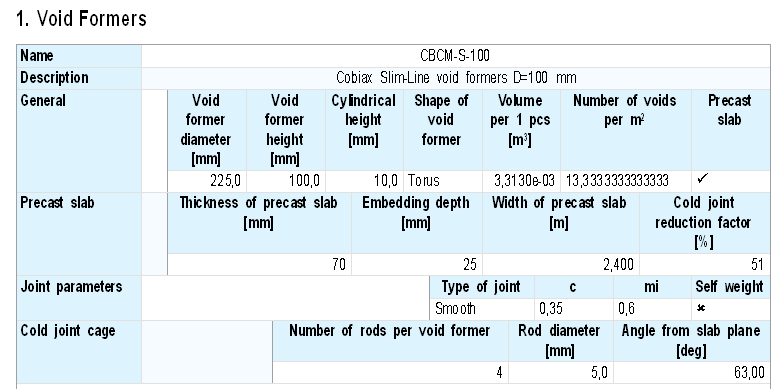
Table with voided slab is not added to file default.tdx.