![]()
|
||
|
|
||
In order to be able to design the pad foundation, it is necessary to switch on the following functionality in the Project data dialogue:
The partial safety factors for the combination are defined in the Manager for National annexes. It can be opened from the Basic project data dialogue.
Available are factors for Set B of the EN-ULS (STR/GEO) combination defined in EN 1990 [Ref.4]. In addition, for Geotechnical analysis, also Set C needs to be supported. Therefore the Combination Setup is expanded as follows:
The set C uses the following defaults:
|
Safety Factor |
Default (Set C) |
|
Partial factor permanent action - unfavourable |
1,00 |
|
Partial factor permanent action - favourable |
1,00 |
|
Partial factor for prestress action - favourable |
1,00 |
|
Partial factor for prestress action - unfavourable |
1,20 |
|
Partial factor leading variable action |
1,30 |
|
Partial factor accompanying variable action |
1,30 |
|
Partial factor for shrinkage action |
1,00 |
Note that the Reduction factor input field is NOT available for this Set C.
A new combination is added: EN-ULS (STR/GEO) Set C
This combination follows exactly the same rules as the EN-ULS (STR/GEO) Set B except for the following differences:
The Combination Setup for ‘6.10’ or ‘6.10a & 6.10b’ is not used for this combination. For this combination always ‘6.10’ is used.
The safety factors are taken from the column Set C of the Combination Setup.
By default SCIA Engineer creates the following automatic classes:
A new class is generated automatically: GEO. This class contains all combinations of the following types:
EN-ULS (STR/GEO) Set B
EN-ULS (STR/GEO) Set C
The class is only generated in case the functionality ‘Subsoil’ is activated in the Project Data.
In case none of these combination types are available, the class is not generated.
In case only one of these combination types is available, the class is generated with only those combinations.
The Set C combination is specifically used for Geotechnical Design according to Design Approach 1. Therefore, it should not be added to the default classes for ULS combinations but only to the Soil class.
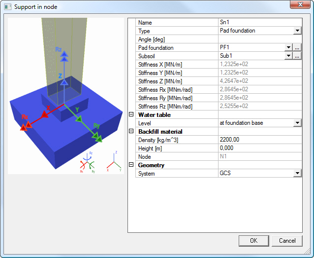
The group Water table contains the water Level:
By default the level is set to No influence.
Backfill material contains the following items:
density = Specifies the density of the soil above the foundation block or strip.
height = It defines the height of the upper soil layer. The height is measured from the top-surface of the foundation block.
The Height [m] input field in the Backfill material group allows for the input of both positive AND negative values. Negative values are required to indicate that the soil is lower than the top of the foundation block.
Stiffnesses are calculated by the program. The formulas applied can be seen in the Theoretical background: page 16 - Annex: Pad Foundation Stiffness
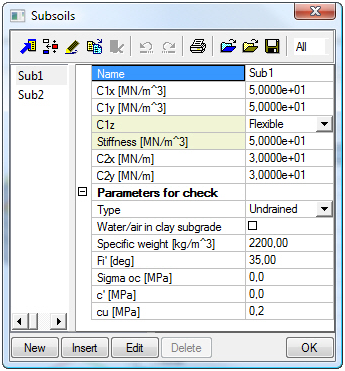
In comparison with previous versions of the program, some Subsoil parameters has been renamed in order to comply with the EN convention:
|
Old text |
New text |
|
Fic [deg] |
Fi’ [deg] |
|
Cc[MPa] |
c’[MPa] |
|
Ccu [Mpa] |
cu [Mpa] |
In addition, a new checkbox Water/air in clay subgrade is added.
Service Geotechnics contains items:
The Geotechnics Setup has the same layout as Setup dialogues for Steel, Aluminium, etc. We kindly refer you to the theoretical background manual for detailed information.
The group Support Reaction Elimination Factors allows the user to eliminate specific support reactions by inputting a multiplication factor. These input fields are limited to values between 0 and 1.
By default all reactions are used (factors 1.00). These factors can be used in case the user for example models only a pad foundation and omits other foundation elements like a ring beam. The user can then specify that only 50% of a reaction should be used to design the pad foundation since the other 50% goes into the ring beam.
The Maximum value of eccentricity group allows the user to specify the maximum allowed eccentricity in function of the width The user can choose between 1/3, 1/6 and No Limit
The checkbox Known soil capacity, use Sigma oc can be used by the user to override the EN 1997-1 bearing calculation. Instead, the inputted Sigma oc value of the subsoil is used..
By default this checkbox is de-activated.
Note that this analysis is NOT according to EN 1997-1.
In addition, under the National Annex button in the Project data dialogue the parameters relating to the national annex can be specified:
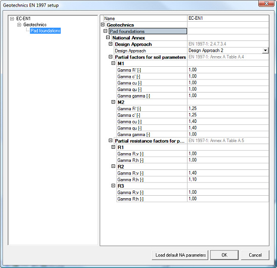
The group Design Approach EN 1997-1: 2.4.7.3.4 contains three options:
The Design Approach determines which set of combinations, safety factors and resistance factors have to be used.
Note: the Design Approach is given here and not on the general tab since the National Annex can give different approaches for different foundation types (for example approach 1 for pad foundations and approach 3 for pile foundations etc).
The group Partial factors for soil parameters contains the safety factors according to Table A.4. Two sets are shown: M1 & M2. These sets have the following default values:
|
Safety Factor |
M1 |
M2 |
|
Gamma Fi’ |
1,00 |
1,25 |
|
Gamma c’ |
1,00 |
1,25 |
|
Gamma cu |
1,00 |
1,40 |
|
Gamma qu |
1,00 |
1,40 |
|
Gamma gamma |
1,00 |
1,00 |
The group Partial resistance factors for pad foundations
contains the resistance factors according to Table A.5. Three sets
are shown: R1, R2 & R3. These sets have the
following default values:
|
Resistance Factor |
R1 |
R2 |
R3 |
|
Gamma R;v |
1,00 |
1,40 |
1,00 |
|
Gamma R;h |
1,00 |
1,10 |
1,00 |
The property window for the Pad foundation stability check allow for the check to be executed ONLY for Result Classes.
By default the class GEO is used.
In case there is no class in the project the class field is empty.
The Selection in this case refers to Pad Foundation entities.
The action buttons perform ‘Refresh’, ‘Preview’ and ‘AutoDesign’.
When executing the check, the safety and resistance factors which are applied depend on the Design Approach set in the Setup.
For Design Approach 1 the class for which the check is executed needs to contain at least one combination of each of the following types:
In case the class for which the user wishes to execute the check does not comply with this requirement, the check is not executed and a warning dialog is shown:
“Note: For Design Approach 1 it is required that the Result Class contains at least one combination of each of the following types:
The selected class does not meet this requirement; please modify the contents of the class.”
For Design Approaches 2 & 3 there is no requirement for the content of the class.
In general three separate checks are executed:
In a special case, instead of the three above a so called Uplift Check is executed.
Before any check can be executed, the required safety and resistance factors need to be determined depending on the chosen Design Approach.
In addition the vertical design loading Vd , horizontal design loading Hd and effective geometry of the pad need to be determined.
In the following paragraphs the checks are specified:
The Bearing check is executed according to [Ref.1] art. 6.5.2 and Annex D

The Bearing resistance Rd depends on the fact whether the soil condition is drained or undrained.
In case the user ‘knows’ the soil capacity, Rd is read directly from the input data instead of being calculated.
The Sliding check is executed according to [Ref.1] art. 6.5.3

The Sliding resistance Rd depends on the fact whether the soil condition is drained or undrained.
The value Rp,d specifies the positive effect of the earth pressure at the side of the foundation. Since this effect cannot be relied upon, this value is taken as zero [Ref.2].
EC7 specifies in art. 6.5.4 that special precautions are required for loads with large eccentricities.
According to [Ref.3] this is done by checking if the design load is within a critical ellipse or critical diamond.
In case the vertical design loading Vd is negative, it implies that the pad foundation is in tension and may thus be ‘uplifted’ from the ground.
It is important to note that this check is executed INSTEAD of the three above checks.
The check is executed for a Result Class.
Depending on the Design Approach set in the Geotechnical Design Setup, the sets of safety factors are read from the setup as follows:
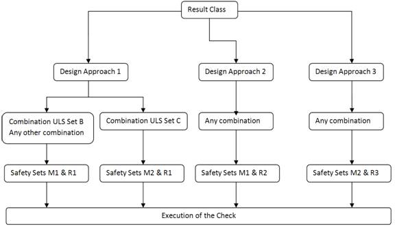
For Design Approach 1 the safety sets depend on the combination
type.
For combinations of type EN-ULS (STR/GEO) Set B sets M1 & R1 are used.
For combinations of type EN-ULS (STR/GEO) Set C sets M2 & R1 are used.
For any other combination sets M1 & R1 are used.
For Design Approach 2, in all cases sets M1 & R2 are used.
For Design Approach 3, in all cases sets M2 & R3 are used.
Note 1: A code combination is internally split into different linear combinations. The check is executed for these linear combinations. It is thus important to retrieve from which code combination type a linear combination was generated in order to know which safety set to apply.
Note 2: The Result Class may off course also contain load cases or non-linear combinations. These are seen as ‘Any combination’ for the check.
Using the above information, the safety factors can be read from the Geotechnics Service and the design values for the soil properties can be determined:
|
Design Value |
Formula |
|
|
With: φ’ read from Subsoil Library γφ’ read from Geotechnics Setup |
|
|
With: c’ read from Subsoil Library γc’ read from Geotechnics Setup |
|
|
With: cu read from Subsoil Library γcu read from Geotechnics Setup |
|
|
With: γ’ specific weight read from Library γ γ read from Geotechnics Setup |
|
|
With: γBackfill weight
read from Pad γ γ read from Geotechnics Setup |
A final safety factor which needs to be determined concerns the safety factor for the weight of the pad foundation and the backfill material. This safety factor is taken as the safety factor for a permanent load for the combination under consideration i.e. gG.
A permanent load can be seen as favourable or as unfavourable. The corresponding safety factor is determined as follows.
- The safety factor of the first permanent load case within an exploded combination is taken as gG . In this way, the correct value is found for any type of combination (code, linear, envelope, non-linear, …).
- In case the exploded combination does not have a permanent load case, gG is taken as 1,00.
The next step in the check concerns the determination of the effective geometry of the pad foundation.
The following picture illustrates the different actions working on the foundation.
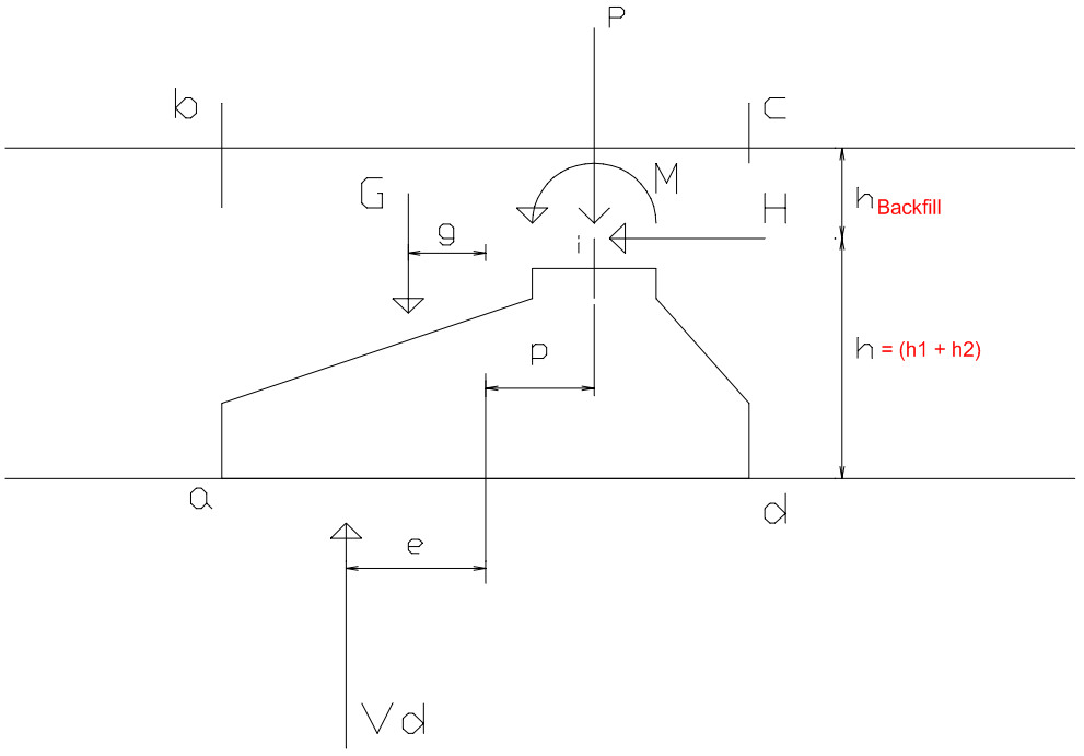
In this picture the following notations are used:
|
Action |
Info |
|
G |
Weight of the foundation and of any backfill material inside the area of abcd. |
|
g |
Load application point for load G referenced to the center point of the foundation base |
|
P |
Vertical Rz reaction of the support |
|
p |
Load application point for load P referenced to the center point of the foundation base. This is read as the load eccentricities ex and ey from the Pad Foundation library. |
|
H |
Horizontal Rx or Ry reaction of the support |
|
h |
=(h1 + h2) Load application point of the horizontal load H referenced to the foundation base. With h1 and h2 read from the Pad Foundation Library. |
|
M |
Moment Mx or My reaction of the support |
|
Vd |
= G + P Ultimate load vertical to the foundation base including the weight of the foundation and any backfill material. |
|
e |
Load application point for load Vd referenced to the center point of the foundation base |
The reaction forces Rx, Ry, Rz, Mx, My need to be multiplied with the Support Reaction Elimination factors.
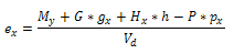
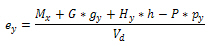
The eccentricity e can be calculated as follows:
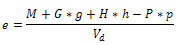
For a general 3D case this formula is written as:
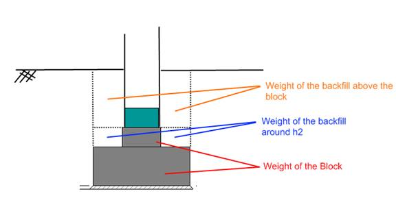
The weight G consists of three parts:
1) The weight of the foundation block, GBlock
This depends on the shape of the block (prismatic or pyramidal), dimensions and also the density gBlock of the block material.
All these data can be
read from the Pad Foundation Library.
The density of the block depends on the Water table level.
|
· Water level |
· Block Density |
|
No influence |
γBlock |
|
at foundation base |
γBlock |
|
at ground level |
(γBlock –γW) |
The Water Density gW
is taken as 9,81 kN/m³
2) The weight of the backfill around h2, GBackfill,Around
This depends on the shape of the block (prismatic or pyramidal), dimensions and also the density of the backfill material.
All block data can be read from the Pad Foundation Library.
The density of the backfill depends on the Water table level.
|
· Water level |
· Backfill Density |
|
No influence |
γBackfill,d |
|
at foundation base |
γBackfill,d |
|
at ground level |
(γBackfill,d – γW) |
The Water Density
gW is
taken as 9,81 kN/m³
3) The weight of the backfill above the foundation block, GBackfill,Above
This depends on the height and density of the backfill as specified in the input of the Pad Foundation.
Note that the height of the backfill material can also be negative. Negative values are required to indicate that the soil is lower than the top of the foundation block.
The three parts are illustrated on the following picture:
The design value of the total weight G can then be calculated as follows:
Gd = gG * [GBlock + GBackfill,Around + GBackfill,Above]
With gG the safety factor of the permanent loading for the combination under consideration.
Distances gx & gy
Using the weight and the volume, the center of gravity of the block and backfill can be determined. The distances gx and gy are then calculated from this centroid to the center point of the foundation base.
Effective Geometry
As a final step, using the eccentricities ex and ey the effective geometry of the foundation base can be calculated as follows:
L1 = A – 2 * |ex|
L2 = B – 2 * |ey|
With A & B read from the Pad Foundation library.
B’ = min (L1 ; L2)
L’ = max (L1 ; L2)
A’ = B’ * L’
In case B’ < 0 m or L’ < 0 m the geometry is incorrect.
In this case, the check is not executed and a warning is given on the output:
“Warning: The check cannot be executed due to incorrect effective geometry dimensions. Please review the base dimensions of the pad foundation!”
The formulas in this paragraph are used in case the Type field in the Subsoil Library is set to Undrained.
The design value of the undrained bearing resistance is calculated as follows:
|
Value |
Formula |
|
cud |
|
|
bc |
Inclination of the foundation base (always horizontal base in SE) = 1,00 |
|
sc |
Shape of the foundation (rectangular shape)
|
|
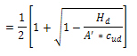
ic |
Inclination of the load, caused by horizontal load Hd
and Hd≤ A’ * cud in case Hd > A’ * cud the value of ic can be set to 0,5 |
|
Hd |
Resulting horizontal load
|
|
Hx |
Horizontal support reaction Rx. |
|
Hy |
Horizontal support reaction Ry. |
|
B’ |
Effective width. |
|
L’ |
Effective length. |
|
A’ |
Effective area. |
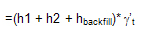
|
q |
Overburden at the foundation base [Ref.5] =(h1 + h2 + hbackfill)* gBackfill,d With: h1 & h2 read from the Pad Foundation Library hbackfill read from the Pad Foundation input gBackfill,d as defined earlier in this document. |
|
gR,v |
Resistance factor read from the Geotechnics Setup |
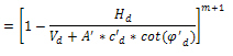
The formulas in this paragraph are used in case the Type field in the Subsoil Library is set to Drained.
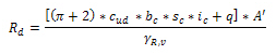
The design value of the drained bearing resistance is calculated as follows:

|
Value |
Formula |
||||||||
|
cd’ |
As specified earlier in this document. |
||||||||
|
Nc |
Bearing resistance factor
|
||||||||
|
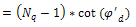
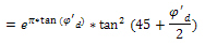
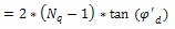
Nq |
Bearing resistance factor
|
||||||||
|
Ng |
Bearing resistance factor
|
||||||||
|
bc |
Inclination of the foundation base (always horizontal base in SE) = 1,00 |
||||||||
|
bq |
Inclination of the foundation base (always horizontal base in SE) = 1,00 |
||||||||
|
bγ |
Inclination of the foundation base (always horizontal base in SE) = 1,00 |
||||||||
|
sc |
Shape of the foundation (rectangular shape)
|
||||||||
|
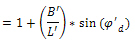
sq |
Shape of the foundation (rectangular shape)
|
||||||||
|
sγ |
Shape of the foundation (rectangular shape)
|
||||||||
|
ic |
Inclination of the load, caused by horizontal load Hd
|
||||||||
|
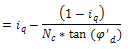
iq |
Inclination of the load, caused by horizontal load Hd
|
||||||||
|
ig |
Inclination of the load, caused by horizontal load Hd
|
||||||||
|
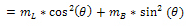
m |
|
||||||||
|
mL |
|
||||||||
|
mB |
|
||||||||
|
q |
Angle of the horizontal load Hd with the direction L’ |
||||||||
|
|
As specified earlier in this document. |
||||||||
|
B’ |
Effective width as defined earlier in this document. |
||||||||
|
L’ |
Effective length as defined earlier in this document. |
||||||||
|
A’ |
Effective area as defined earlier in this document. |
||||||||
|
Hd |
Resulting horizontal load
|
||||||||
|
Hx |
Horizontal support reaction Rx. |
||||||||
|
Hy |
Horizontal support reaction Ry. |
||||||||
|
Vd |
As specified earlier in this document. |
||||||||
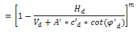
|
q’d |
Effective overburden at the foundation base [Ref.5]
With: h1 & h2 read from the Pad Foundation Library hbackfill read from the Pad Foundation input γ’t is depending on the water level as follows:
γBackfill,d as defined earlier in this document. γW is taken as 9,81 kN/m³ |
||||||||
|
|
Effective weight density of the soil below the foundation level depending on the water level as follows:
γ’ d as defined earlier in this document. γW is taken as 9,81 kN/m³ |
||||||||
|
γR,v |
Resistance factor read from the Geotechnics Setup |
In case the Soil capacity is known, this value can be used directly instead of using the EC7 bearing resistance calculation.
This procedure is applied in case the checkbox Known soil capacity, use Sigma oc is activated in the Geotechnical Design Setup.
The design value of the bearing resistance is calculated as follows:

|
Value |
Formula |
|
A’ |
Effective area as defined earlier in this document. |
|
σod |
Design value of the admissible soil capacity, taken as soc |
|
σoc |
Read from the Subsoil Library |
The sliding resistance is dependent on the condition of the subsoil.
a) In case the Type field in the Subsoil Library is set to Undrained.

|
Value |
Formula |
|
cud |
As specified earlier in this document. |
|
A’ |
Effective area as defined earlier in this document. |
|
γR,h |
Resistance factor read from the Geotechnics Setup |
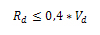
In case the checkbox Water/air in clay subgrade in the Subsoil Library is activated, the value of Rd is limited as follows:
|
Value |
Formula |
|
Vd |
As specified earlier in this document. |
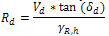
b) In case the Type field in the Subsoil Library is set to Drained.
|
Value |
Formula |
||||||
|
Vd |
As specified earlier in this document. |
||||||
|
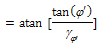
δd |
Design friction angle at the foundation base Dependent on the Cast condition specified in the Pad Foundation Library:
|
||||||
|
|
As specified earlier in this document. |
||||||
|
γR,h |
Resistance factor read from the Geotechnics Setup |
To prevent special precautions according to art. 6.5.4 the eccentricity of the load shall not exceed 1/3 or 1/6 of the width.
The maximal value of the eccentricity is defined in the Geotechnical Design Setup.
a) In case the maximal eccentricity is set to 1/3
b) In
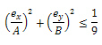
case the maximal eccentricity is set to 1/6

|
Value |
Formula |
|
ex |
As specified earlier in this document. |
|
ey |
As specified earlier in this document. |
|
A |
Read from Pad Foundation Library |
|
B |
Read from Pad Foundation Library |
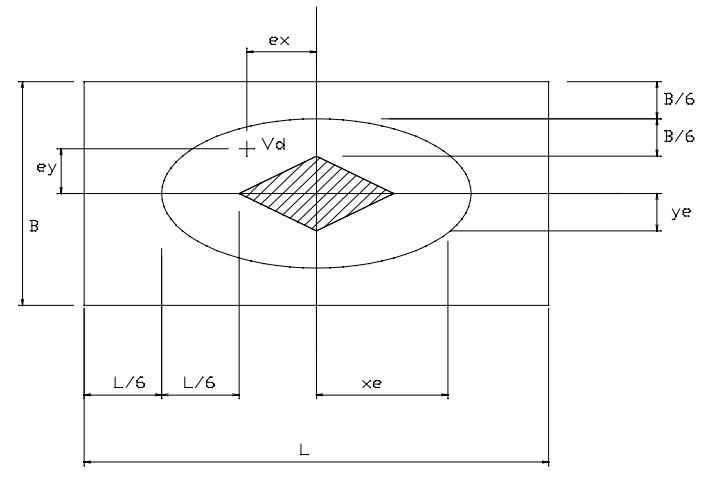
c) In case the maximal eccentricity is set to No limit
In this case there is no limit i.e. any eccentricity is allowed. The unity check is set to 0,00.
In case the vertical design loading Vd is negative, it implies that the pad foundation is in tension and may thus be ‘uplifted’ from the ground.
The uplift check can be written out as follows:

|
Value |
Formula |
|
P |
The vertical Rz reaction as specified earlier in this document. |
|
Gd |
The weight of the foundation and any backfill as specified earlier in this document. |
Both a Brief and Detailed output are available with table composer support.
Unity check values exceeding 1.00 is shown in bold.
For optimizing the pad foundation, the sensitivity optimization and grid are used as implemented for Steel.
Pad foundation optimization is added both in the Pad Foundation Stability Check Service as well as in the Overall Optimization Solver.
The maximal check limit is configurable for each of the three main checks:
- Maximal check on bearing
- Maximal check on sliding
- Maximal check on eccentricity
By default, the maximal value for each of the three checks is set to 1,00. Note that all three input fields should only allow the input of positive values.
For each of the three checks a Maximal unity check field is shown which shows the current value of the unity check.
The picture shows the pad foundation geometry and is taken from the Pad Foundation Library. In the same way as it is done in steel, during the optimization, the dimensional changes are shown in the picture.
The Change Pad foundation button opens the Pad Foundation Library and allows the user to modify the pad foundation or select a different one. It functions in the same way as the Edit button in the steel optimization.
The Next down and Next up buttons function in the same way as for steel, the selected grid parameter is modified up or down one step.
The Search for optimal button function in the same way as for steel, the selected grid parameters are optimized.
The Direction combo functions in the same way as for steel. The user can choose to set it to ‘Up & down’ so the AutoDesign works in two directions or the user can set it to ‘Only up’ so the AutoDesign can only increase the parameters. By default the combo is on ‘Up & down’.
The Parameter combo allows the user to set which parameter(s) should be optimized. The user can choose any of the pad foundation dimensions or set the combo to Advanced AutoDesign which allows the optimization of several parameters together (Sensitivity).
The parameters are A, B, h1, h2, h3, a, b, ex and ey.
By default the combo shows the A parameter.
The optimization grid has the same layout as used for steel except for the ‘Sort By’ column which is removed.
The grid itself functions in the same way as the grid for steel.
In the same way as for steel, the user can assign a Dimension List to a parameter. During AutoDesign, only values from the list are used.
The Set value button can be used to modify a selected parameter from the grid. In the same way as for steel, the dialog which appears depends on whether the list has been assigned to the selected parameter or not.
Using Select/Deselect All the user can quickly select or deselect all parameters in the grid.
As in steel, parameters can be set in relation to one another. The user can use the Test relations button to check if no loops have been made.
Important remark: in steel, several validity tests are run when starting the AutoDesign, for example the test on relations is done automatically. The same tests are also executed automatically for pad foundations.
The Advanced AutoDesign itself uses the Sensitivity algorithm:
- Within each iteration, each parameter is changed separately with its step and it is evaluated which change has the most influence on the Pad foundation utilization. This one is then taken and applied.
The procedure is then repeated in the next iteration until the Pad foundation has a unity check below 1,00.
- When below 1,00 the same procedure is applied (changing each parameter separately with its step) but now the goal is to get as close to 1,00 as possible and not to go over 1,00. This means that the parameters will now be decreased in value.
- In the end, a situation is reached where no parameter can be decreased with its step anymore since this will lead to a unity check above 1,00. This is then the most optimal solution.
|
[1] |
EN 1997-1, Eurocode 7: Geotechnical design – Part 1: General rules, CEN, 2004. |
|
[2] |
Frank R., Baudoin C., Driscoll R., Kavvadas M., Krebs Ovesen N., Orr T., Schuppener B., Designer’s Guide to EN 1997-1 Eurocode 7: Geotechnical design – Part 1: General rules, Thomas Telford, 2004. |
|
[3] |
Schneider K.-J., Bautabellen für Ingenieure, 13. Auflage, Werner Verlag, 1998. |
|
[4] |
EN 1990, Eurocode – Basis of Structural Design, CEN, 2002. |
|
[5] |
Lambe T., Whitman R., Soil Mechanics, MIT, John Wiley & Sons, Inc, 1969. |