![]()
|
||
|
|
||
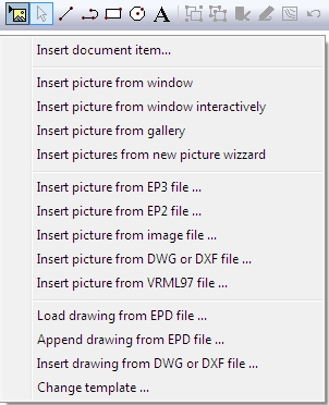
A picture may be inserted from various resources:
|
Insert picture from window |
Inserts the drawing from a required graphical window. |
|
Insert picture from EP3 file |
Inserts a picture from EP3 file. |
|
Insert picture from EP2 file |
Inserts a picture from EP2 file. |
|
Insert picture from BMP file |
Inserts an external Windows bitmap file. |
|
Insert picture from DWG or DXF file |
Inserts a picture from DWG or DXF file. The contents of the file is inserted as a picture, i.e. including a frame. |
|
Load from EPD file |
Loads a previously saved graphic output drawing. |
|
Append from EPD file |
Appends a previously saved graphic output drawing. |
|
Insert drawing from DWG or DXF file |
Inserts a drawing from DWG or DXF file. The contents of the file is inserted as a set of drawn entities grouped into one group. |
|
Changes the template of the drawing. |
The user may control the way an external Windows bitmap is inserted into the graphic output drawing. Function Insert picture from BMP file opens a dialogue where the parameters controlling the insertion may be adjusted.
|
Original picture |
Shows the original picture saved on disk. |
|
Preview |
Shows the picture with adjusted effects taken into account. |
|
Ignore aspect ratio |
If selected, the inserted picture is fitted (distorted) into the user-specified area. If not selected, the inserted picture keeps the original aspect ration. |
|
Greyscale |
The picture (if coloured) is reduced to greyscale picture. |
|
Watermark |
The picture is inserted as a watermark. |
While options Ignore aspect ration, Greyscale, and Watermark have effect only on the Preview window of the dialogue, the selected Stretch mode affects both the Original picture and Preview windows of the dialogue.
Concerning BMP files, only 24-bit bitmaps can be inserted.
Concerning DXF and DWG files, only drawings created in AutoCAD versions 2000 and older can be imported. If a drawing created in AutoCAD 2004 and possible newer versions is imported, the result may not be satisfactory. This is due to modifications in the file format definition. The format definition varies for different AutoCAD versions.
The procedure for the insertion of an external drawing may vary by individual function.
Generally there are four procedures: (i) for insertion of a picture (including a picture created from a DXF/DWG drawing), (ii) for insertion of a drawing (including a DXF/DWG drawing), (iii) for loading of EPD drawing and (iv) for appending of EPD drawing.
EPD is a specialised graphical format developed by SCIA Company..
 )
on the control toolbar of the Graphic
output dialogue.)
on the control toolbar of the Graphic output dialogue.)
on the control toolbar of the Graphic output dialogue.)
on the control toolbar of the Graphic output dialogue.
)
on the control toolbar of the Graphic
output dialogue.)
on the control toolbar of the Graphic output dialogue.)
on the control toolbar of the Graphic output dialogue.)
on the control toolbar of the Graphic output dialogue.