![]()
|
||
|
|
||
Prior to the introduction of hanging nodes, the projection normal (perpendicular) to the structural member was observed as insufficient due to the problems with recalculation of strain load of tendon to structural member in some cases. These cases you can see on following figures.
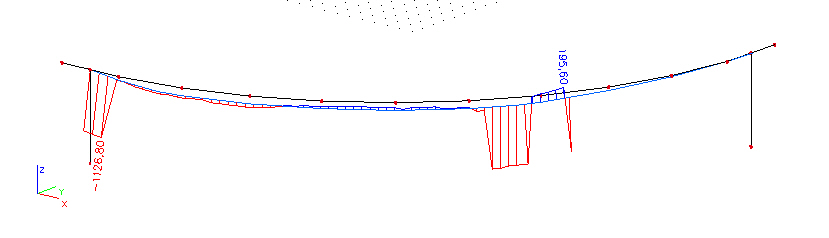
fig.1 Normal force from prestressing in curved bridge
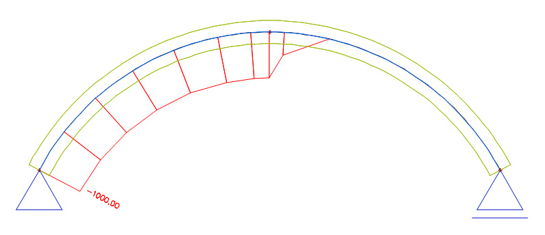
fig.2 Normal force - arch
That’s why concept of hanging nodes was proposed. Hanging nodes is term used in finite element method describing interpretation of the element on the mesh. The mesh of the tendon and attached elements (1D beam or rib) is independent. The tendons are modelled as 1D memebr on eccentricity in case without using hanging nodes. When the hanging nodes are used then stiffness of the tendon is added to the closest mesh element according to type of projection.
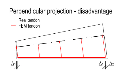
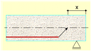
fig.3 Real and FEM tendon in perpendicular projection
General idea is that user doesn’t want to build the model via inserted lines and macros. The way of tendon allocation to 1D members. Therefore a concept of “hanging nodes” was proposed. The stiffness of the tendon (and its load) is distributed into the individual nodes of 1D or 2D member. Similar concept would consistently be accepted for 3D volume.
Two possibilities of tendon projection to the structural member are available:
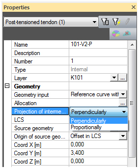
fig.4 Two types of projection in 1D
1. Perpendicular projection to the structural member
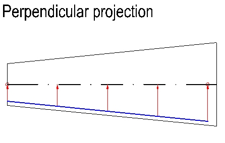
fig.5 Perpendicular projection
2. Proportional projection in proportion of lengths of tendon and element 1D (or selected elements). Internal (hanging) nodes of tendon finite elements are also generated proportionally.
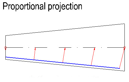
fig.6 Proportional projection
That is to say the links between internal points of the tendon and element 1D will also be proportional. Therefore additional functionality and input data were required in for the allocation:
a. The selection of structural members, to which the tendon is allocated, must be done with respect to their order
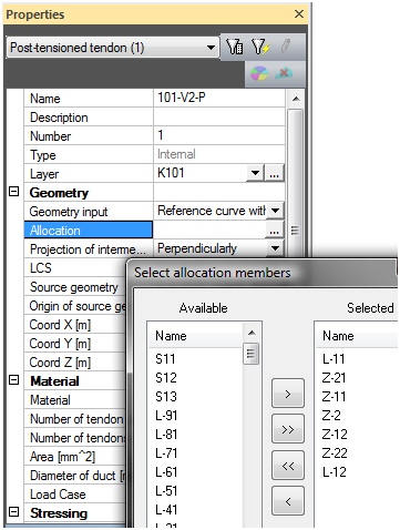
fig.7 Allocation of member
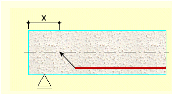
b. The possibility to fix selected point of the tendon to selected point of the element 1D. Then it is necessary to define the point on first 1D element (e.g. by distance from the beginning) to which the beginning of the tendon is fixed, and the point on last 1D element to which the end of the tendon is fixed.
Projection of intermediate points – this option is relevant only in case of Hanging nodes
• Proportionally – user defines the length where the tendon effects are projected on
o Way of location – begin
First node – the beginning of projected tendon effects to the beam is from the first node of the allocated beam
Location – distance from the beginning of the beam
o Way of location – end
Last node – the beginning of projected tendon effects to the beam is to the last node of the allocated beam
Location – distance from the end of the beam
• Perpendicularly – tendon is projected directly in perpendiculars to the beams
1 Existing way of modelling (with respect to the mesh, …) is kept for TDA, and external (free) unbonded post-tensioned tendons.
2 Optionally the possibility of modelling with respect to the mesh is available also for standard FEM solver.
3 All types of presentation of the results and prestressed concrete checks are not affected.
4 New way of the modelling is fully compatible with standard construction stages, and mobile load analysis, but not available for TDA calculation
1.3 Setting for using Hanging nodes
The using hanging node for 1D member is possible to set in Mesh setup
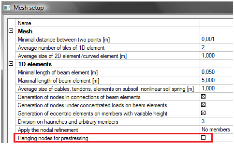
fig.8 Settings for hanging nodes
This functionality enables to user attach internal post-tensioned tendons directly to 2D slab and shell elements. No dummy beam 1D (rib) is necessary. The mesh of internal post-tensioned tendon and attached 2D elements can be independent.
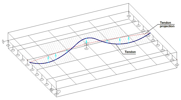
fig.9 Tendon defined on slab
For tendons allocated on 1D members (beams) is possible to projection the tendon perpendicularly on beam or proportionally. For tendons allocated on 2D members (slabs) is perpendicularly projection only.
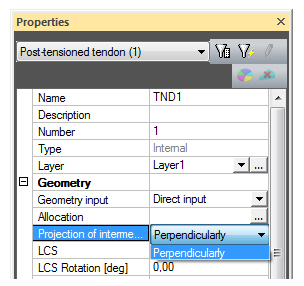
fig.10 Proportional projection for 2D members only
Tendons can be allocated either on beams or on slabs. The tendon geometry on 1D members: source geometry (SG), direct input (DI), reference line with SG (RLSG). The tendon geometry on 2D members: DI or RLSG.
• (SG) is possible to entry tendon only on the 1D member (beam) –> the selective filter.
• (DI) – after geometry entry of the tendon follows the allocation on the members. In allocation list are:
o only 1D members = OK
o only 2D macro = OK + 2D macros must be in the same plane – the verification is done
o both from user (1D, 2D) = warning “In allocation can be either 1D members or 2D members”
The converting of the tendon geometry from DI to SG isn’t possible, if the tendon is on 2D macros.
The using hanging node for 2D member is possible to set in Mesh setup
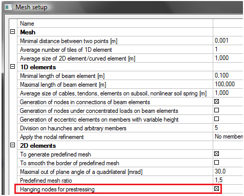
fig.11 Settings for hanging nodes.