Open topic with navigation

Geometry
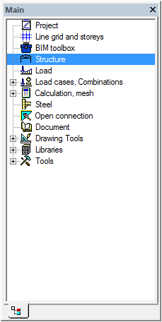
Structure input
- Double-click on Structure in the Main window.
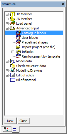
- To enter a new frame, use the option Advanced Input and Catalogue Blocks in the Structure menu. The Catalogue block manager is opened.
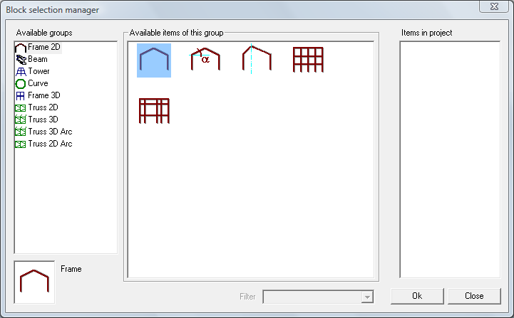
- In the Available Groups choose a Frame 2D
- In the Available items of this group choose the first option (frame).
- Confirm your choice with [OK]. The Geometry block window appears.
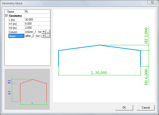
- Enter the frame dimensions: L = 30m, H1 = 6m and H2 = 2m
- In the pull-down menus, choose CL1 for the RL1 for the Beam.
- Confirm your input with [OK]. The Catalogue block manager appears.
- Click [OK] to return to the project.
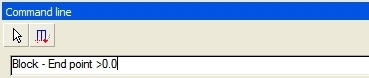
- Left column origin is used as an input point of the frame. Type the coordinates 0 0 0 in the Command line and press <Enter> to confirm your input.
- End the input with the <Esc> key.
The properties of selected elements are shown and can be modified in the Properties window.
If no section has been defined in the project, the New cross-section window will automatically appear, as soon as you will try to enter a structural element (column, beam…).
You can end your input by pressing either the <Esc> key either the right mouse button.
With Zoom All icon in the toolbar, you can visualize the entire structure.
For coordinates separation use <space> key ¨ ¨.
Structure modification
System line alignment
- Select all members
- Set Member system-line at to top in Property window.
- Finish selection with <Esc> key.
LCS Rotation
- Select right column
- Set value of LCS rotation to 180 [deg] in Property window.
- Finish selection with <Esc> key.
- Switch on Show/hide surfaces button.
- Switch on Render geometry button.
- Check generated structure
Rafters splitting
- To split rafter beam into more parts use an option Break in defined points from Modify tab in the Main menu.
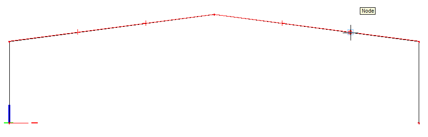
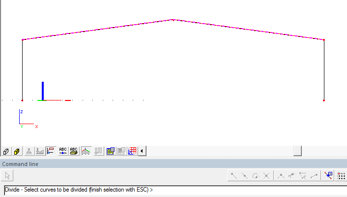
- Select both rafter beams and finish selection with <Esc> key.
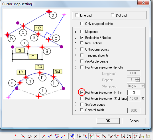
- Click on the button. The Cursor snap setting manager is opened.
- Activate option Points on line-curve and set it’s value to 3.
- Select all rafter points on line.
- Finish selection with <Esc> key.
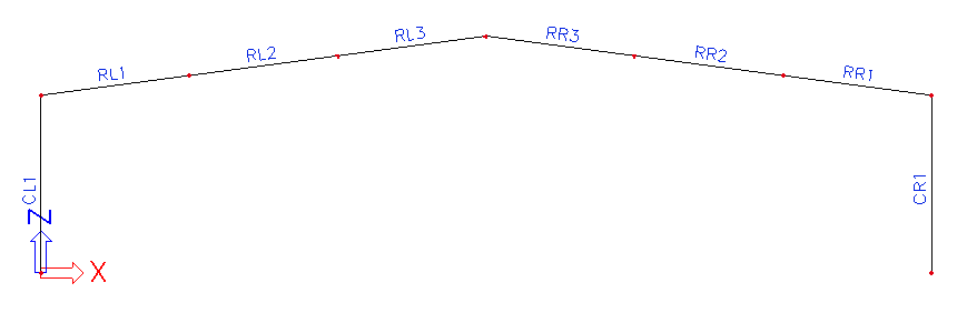
- Select left middle rafter beams and change CSS to RL2 in Property window.
- Finish selection with <Esc> key.
- Repeat points 7 and 8 to set cross-sections according to the following drawing :
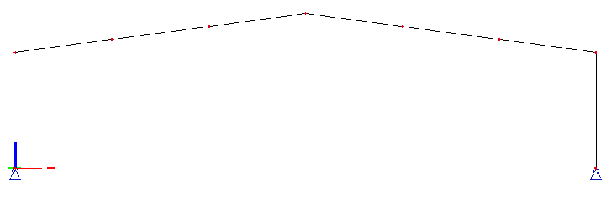
Supports
The geometry input can be completed with supports definition.
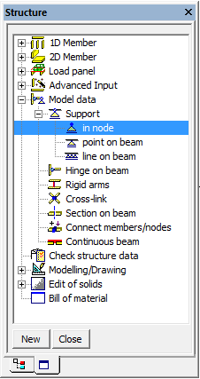
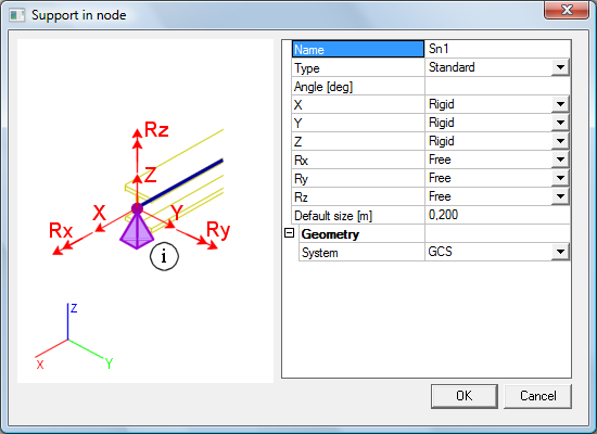
- To enter supports, use the option Main window→Structure→Model data→Support→in node
- Define all support translations Rigid and rotations Free.
- Confirm your input with [OK].
- Select both column bases and press <Esc> to finish the selection.
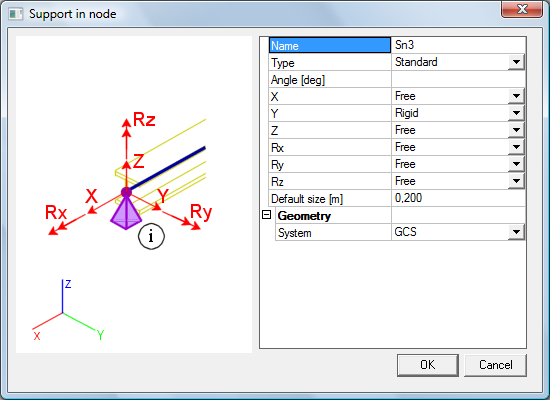
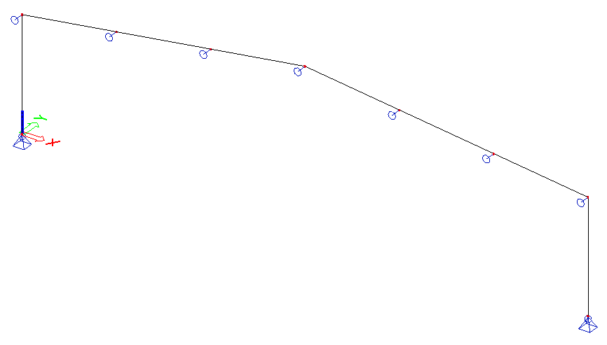
- Use the previous workflow and define supports in remaining nodes with the following settings:
Open topic with navigation
 in the toolbar, you can visualize the entire structure.
 Show/hide surfaces button.
 Render geometry button.
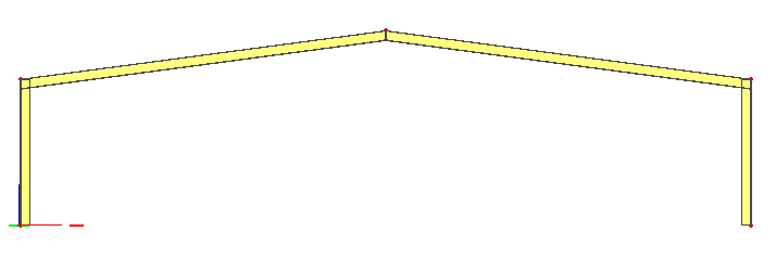
 button. The Cursor snap setting manager is opened.