![]()
|
||
|
|
||
This chapter describes the theoretical background for the available types and behaviours of 2D members in SCIA Engineer.
At this time, SCIA Engineer offers two types of very similar objects:
Load panels are a long known feature of SCIA Engineer. Their behaviour and features remain unchanged.
2D members with element type = Load panel offer the same basic functionality as load panels, plus some extensions:
For more details, read the following text. However, please keep in mind, that the two types of objects mentioned above are distinct and must not be confused.
In SCIA Engineer, a 2D member can have one of the following types:
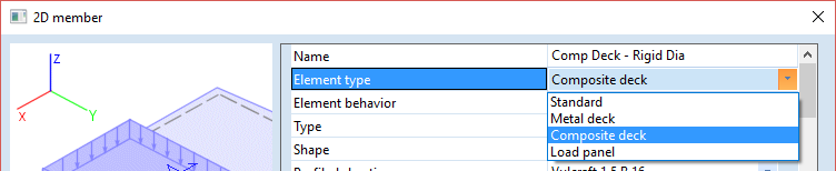
| Standard | Standard 2D member, used for the analysis of generic plates, walls, shells. Its properties are typically defined by a thickness (uniform or variable) and a material. |
| Metal deck |
2D member with settings dedicated for the analysis of metal decks, i.e. deck made of a profiled steel sheeting. The type of sheeting is obtained from a library and its orthotropic properties are calculated from the geometry of the sheeting. This type is supported only for 2D members with a plane geometry. |
| Composite deck |
2D member with settings dedicated for the analysis of composite decks, i.e. deck made of a profiled steel sheeting with a concrete topping. The type of sheeting is obtained from a library. The orthotropic properties of the deck are calculated from the geometry of the sheeting. This type is supported only for 2D members with a plane geometry. |
| Load panel |
Virtual surface for the application of loads. Its purpose is to transmit loads to the structure, without introducing any additional stiffness into the model. See the chapter related to load panels for more information. This type is supported only for 2D members with a plane geometry. |
The Load panel element type is available only in the 64-bit version of SCIA Engineer. To use a load panel in the 32-bit version, create a load panel directly from the dedicated options in the structure service tree.
A 2D member can have one of the following behaviours:
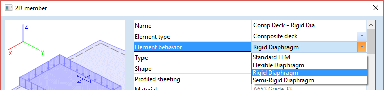
Diaphragm element behaviours are available only for element types Composite deck and Metal deck
See a comparison of the in-plane behaviour of various diaphragm types in Composite Analysis Model: Diaphragm Types.
The following table summarizes the features of the various element behaviours. The load panel element type is added at the bottom of the table, as it also has its own special behaviour.
| Behaviour | Bending stiffness | In-plane stiffness | Load transfer | Self-weight |
| Standard FEM | FEM | FEM | FEM | yes |
| Rigid diaphragm | none | infinite | load panel | yes |
| Semi-rigid diaphragm | none* | FEM | load panel | yes |
| Flexible diaphragm | none* | FEM (no shear) | load panel | yes |
| Load panel | none | none | load panel | no |
* unlike for rigid diaphragms, the bending stiffness of flexible and semi-rigid diaphragms is actually not zero. Such diaphragms are taken into account in the analysis model as a Standard FEM 2D member with a reduced bending stiffness (default = 1/1000 of nominal bending stiffness). Additionally, for flexible diaphragms, the in-plane shear and Poisson's components are set to zero (d12 and d33 components of the 2D orthotropy matrix).
The corresponding, modified orthotropy matrix can be written as follows:

The corresponding, modified orthotropy matrix can be written as follows:

1 Load transfer method must be set to ‘Accurate(FEM), fixed link with beams’ or ‘Accurate(FEM), hinged link with beams’
2 Except for load transfer method ‘Tributary Area’
3 Load can be applied but a warning message explaining that the load will be ignored will be displayed prior to analysis
4 Cannot be applied since a node cannot be added to a load panel
5 Cannot be applied since a load panel is not a 2D member
6 The load is ignored
If a 2D member (with element type set to “Load Panel” or with element behaviour set to “Flexible diaphragm”, “Rigid diaphragm”, or “Semi-Rigid Diaphragm”) has ‘Selection of Entities’ set to ‘User Selection’ and the member is copied, in the newly created copy, the entity selection will be lost (i.e. no entities are selected for load transfer in the copy).
All 2D members (except 2D members with element type set to ‘Load Panel’) will brace and, therefore, affect the buckling length, of any 1D element which they intersect.
When plate ribs are used with a rigid diaphragm, the ‘Average number of tiles of 1D elements’ (Mesh setup) should be set to 4 or higher in order to obtain accurate results. If a rigid diaphragm with plate ribs exists in a project and this number is not set to 4 or higher, a warning message will appear during analysis. By clicking ‘OK’ for this warning message, the program will change this value to 4 automatically.
An integration strip may be added to a 2D member with element type set to “Load Panel” or with element behaviour set to “Rigid diaphragm”, however, since there the 2D member has no physical in-plane stiffness, there are no results available. A warning message will be displayed explaining that results are not available.