Open topic with navigation

Soil-in calculation
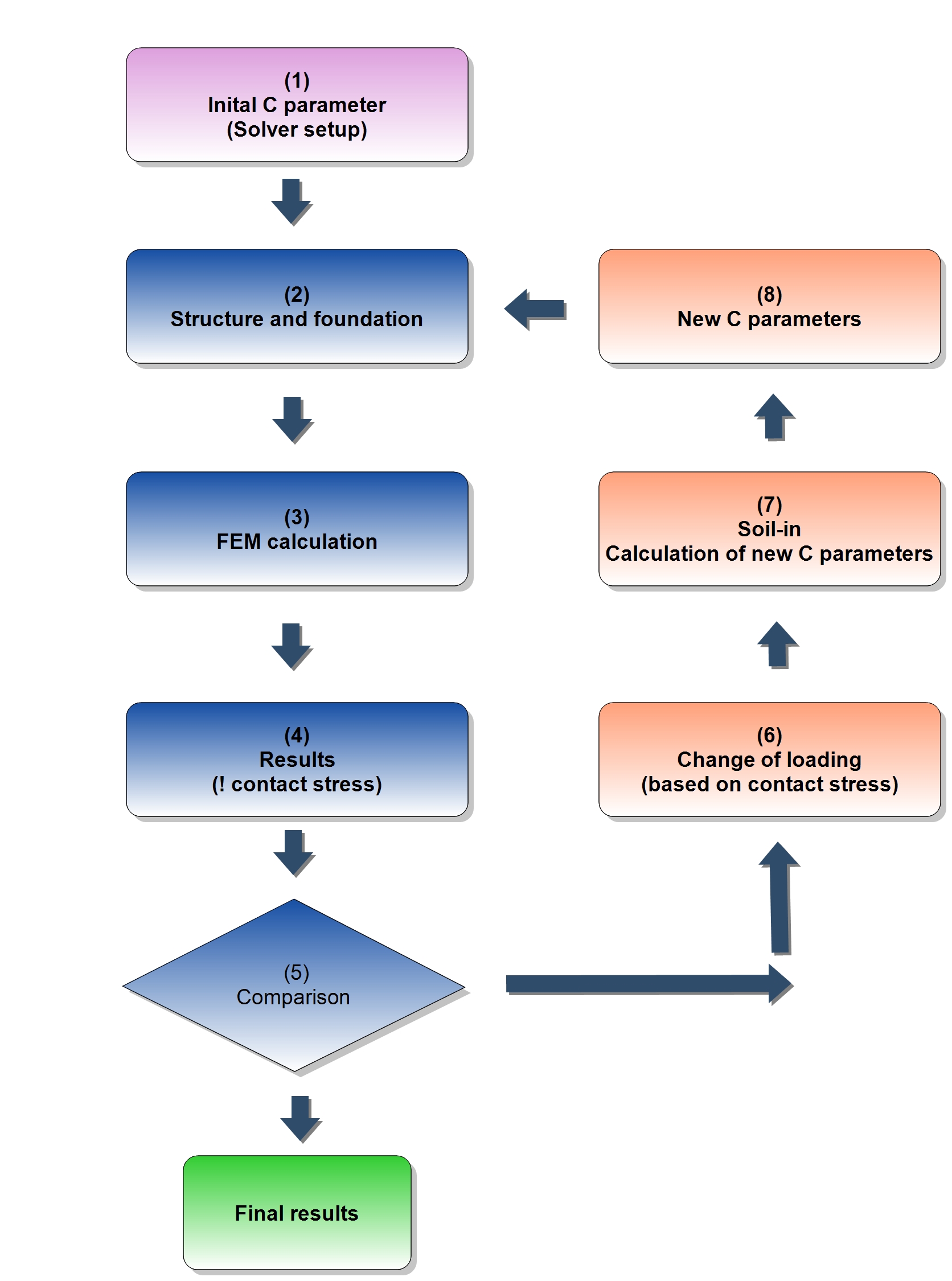
Soil-in iterative cycle
The values from the top structure and the foundation are calculated by FEM. The values are used as the source data for the soil-in.
The iterative process is finished when the contact stress σz and displacement uz does not change significantly in the two subsequent iterations. The special quadratic norms are evaluated in the each iteration cycle to find out if this condition is fulfilled.
Diagram of the iterative cycle:
- The values are taken from the solver setup, predefined by the user.
- Data from the structure and its foundation.
- FEM calculation – important results for soil-in contact stress σz and displacement uz.
- The results of i iteration.
- Comparison of the in contact stress σz and uz – it is based on the quadratic norms, when it does not change significantly, then the calculation is done and SCIA Engineer displays results.
- 1st step of soil-in – the contact stress is recalculated to the new loading.
- 2nd step of soil-in – the C parameters are recalculated, new loading is taken from the previous step.
- 3rd step of soil-in – final C parameters from soil-in - the new input data.
- New C parameters are used for the next FEM calculation.
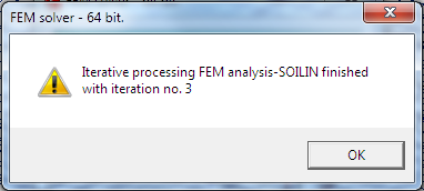
There is a message when the last iteration is done.
Quadratic norm to compare the results from the last and the previous iteration
The calculation of the settlement of the subsoil and subsequent determination of the C parameters is performed in a standard way using an iterative process. The result of this process is the state in which the contact stress or displacement uz in two subsequent iterations does not change significantly. For that reason, the following quadratic norms are evaluated in every j-th iteration:
Where:
nnumber of nodes
σz,icontact stress in node i
Aiarea corresponding to node i
uz,iglobal displacement of node i in the z-direction
The iterative calculation is stopped if εσ<0,001 or εu<0,001
Theory about the derivation process
In this text we limit ourselves to a brief derivation for the purpose of the explanation that will follow:
- The formula for the potential energy of internal forces of the 3D model has the following form:
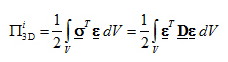
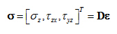
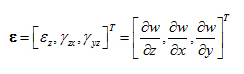
- Neglecting the effect of horizontal components of deformation, we get the following vectors:
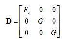
- This means the corresponding simplification of the matrix of physical constants D.
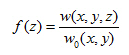
- In order to be able to reduce the problem from 3D to 2D, it is necessary to integrate formula 1) over the z-axis. For this reason, a certain “damping function” fz is introduced and it is defined by the ratio of the settlement in the given depth to the settlement of the surface w0(x,y).
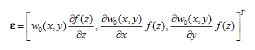
- Modifying formulas from step 2) we get:
- Substituting formula from step 5) into the formula for the potential energy of body V=ΩH, where Ω is the extent of the 2D model and H is the depth of the deformed zone of the 3D model, we obtain the following formula:
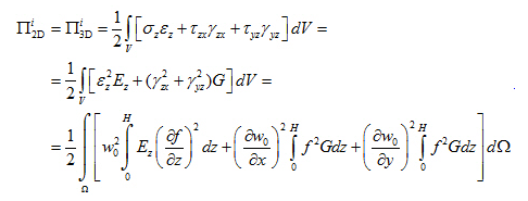
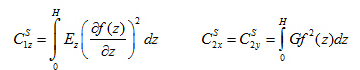
- Integrating over z , we get the formula for the potential energy of internal forces of the 2D model with two parameters C1S and C2S:
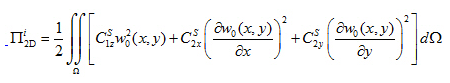
- Comparing formulas from step 6) and 7), we can define the relation between the parameters of the general (3D) and surface (2D) model:
Conclusion:
It is also possible to eliminate the automatic calculation of some C parameters and define them manually. This can be achieved by special adjustment of the subsoil parameters and set the type to Both (!).
Open topic with navigation