![]()
|
||
|
|
||
The forces from FEM analysis (nx,ny, nxy,mx, my, mxy) calculated in direction of LCS has to be recalculated to dimensional forces, it means forces calculated in direction of reinforcement at upper and lower surface.
The following precondition will be used for calculation of 2D dimensional forces :
The following procedure is used for calculation:
For recalculation dimensional forces the following values are necessary:
The inner lever arm is necessary to know for calculation surface forces. Inner lever arm is calculated in direction of angle of first principal moment (the forces is recalculated to this direction).
The forces for calculation inner lever arm is calculated according to formulas below


|
where |
|
|
nx(y) |
normal force in x(y) direction |
|
mx(y) |
bending moment in x(y) direction |
|
nxy |
membrane shear force |
|
mxy |
twisting moment |
|
α |
angle of first principal moment |
If inner lever arm is not calculated (forces are zero or equilibrium is not found) ,then inner lever arm is calculated according to formula
z = 0,9*d
|
where |
|
|
d |
is effective height , which is calculated according to formula. If mα >=0 then d = dlo else d = dup |
|
dlo |
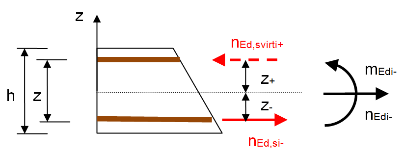
the effective height for lower surface. It is distance the reinforcement at lower surface to upper surface of the element dlo = h-as- |
|
dup |
the effective height for upper surface. It is distance the reinforcement at upper surface to lower surface of the element dlo = h-as+ |
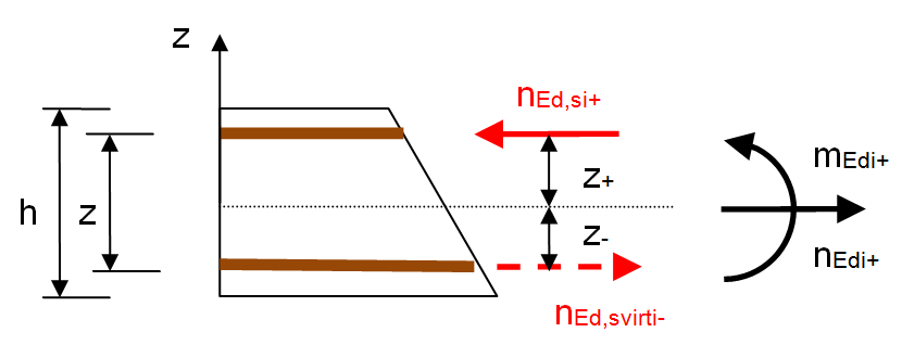
The parts of inner lever arm is calculated according to formulas below:
|
z+ |
the part of lever arm for upper surface (above centre of cross-section) If mα >=0 then z+ is distance of center of compressive concrete to centre of CSS. If mα <0 then z+ is distance of center of tensile reinforcement to centre of CSS. If value z is not calculated (forces are zero or equilibrium is not found) then z+ =0.45d |
|
z- |
the part of lever arm for lower surface (under centre of cross-section) If mα >=0 then z- is distance of center of tensile reinforcement to centre of CSS If mα <0 then z- is distance of center of compressive concrete to centre of CSS . If value z is not calculated (forces are zero or equilibrium is not found) then z- =0.45d. |
The formulas z = z++z- has to be fulfilled for parts of inner lever arm too.
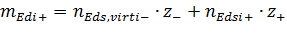
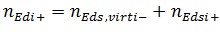
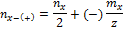
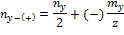
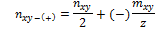
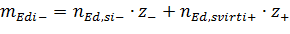
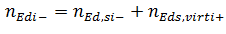
The inputted internal forces is recalculated to both surfaces according the following formulas:
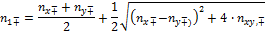
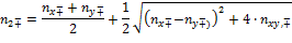
The principal forces at both surfaces are calculated from normal forces at both surfaces according to
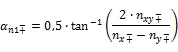
and direction of first principal force is calculated according to formula
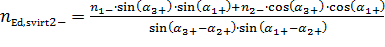
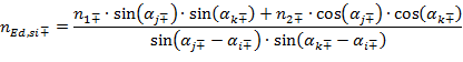
The recalculation the principal forces to inputted direction of reinforcement is done separately for both surfaces with using Baumann’s transformation formula
|
where |
|
|
i, j, k, i |
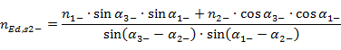
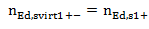
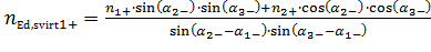
index of direction (direction for recalculation of forces) i, j, k, i = 1,2,3,1 . For example for lower surface and for calculation of forces in second direction α2- (i=2,j=3,k=1-) the formula will be following
|
|
|
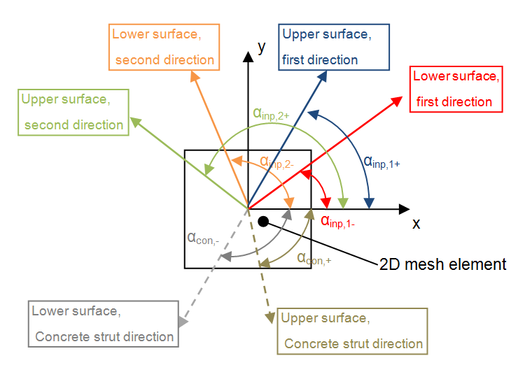
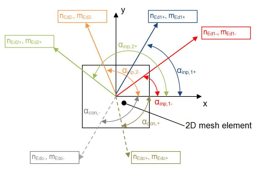
Angle between inputted direction or direction of concrete strut and direction of first principal forces at lower or upper surface The first inputted direction: α1∓= αinp,1∓ – αn1∓ The second inputted direction: α2∓= αinp,2∓ – αn1∓ Direction of concrete strut: α3∓= αcon∓ – αn1∓ |
|
αcon∓ |
The direction of concrete strut at lower (upper) surface. This value can be calculated for all states of stresses excepted of hyperbolic state of stress (n1∓> 0 and n2∓< 0) according to formula: αcon∓ = 0,5·( αinp,1∓ αinp,2∓). For hyperbolic state of stress (n1∓> 0 and n2∓< 0) the angle of concrete strut should be found by optimization method , see next chapter. For the angle of concrete strut, the following conditions have to be fulfilled: (αinp,1∓ +n·180deg) -Δα ≥αcon∓ ≥ (αinp,1∓ +n·180deg) +Δα for n=0,1,2 (αinp,2∓ +n·180deg) -Δα ≥αcon∓ ≥ (αinp,2∓ +n·180deg) +Δα for n=0,1,2 |
Direction of reinforcement for recalculation at lower surface
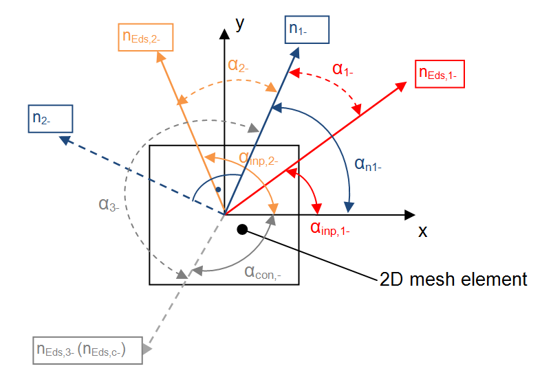
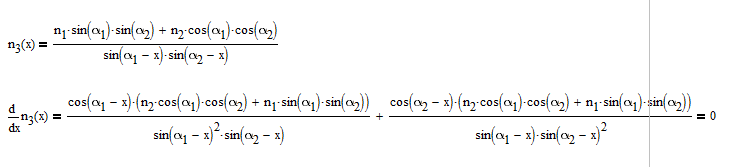
The direction of concrete strut at lower (upper) surface can be calculated for all states of stresses excepted of hyperbolic state of stress (n1∓> 0 and n2∓< 0) according to formula: αcon∓ = 0,5·( αinp,1∓ αinp,2∓). For hyperbolic state of stress (n1∓> 0 and n2∓< 0) the angle of concrete strut should be found by optimization methods. The following rules for optimization angle of concrete strut is used:
(αinp,1∓ +n·180deg) -Δα ≥αcon∓ ≥ (αinp,1∓ +n·180deg) +Δα , n=0,1,2
(αinp,2∓ +n·180deg) -Δα ≥αcon∓ ≥ (αinp,2∓ +n·180deg) +Δα, n=0,1,2
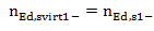
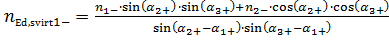
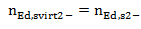
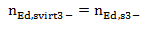
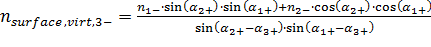
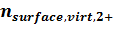
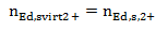
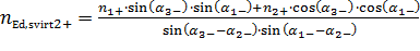
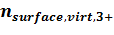
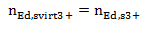
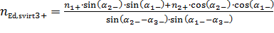
The virtual forces is calculated according to Baumann’s transformation formula, where for virtual forces at lower surface direction of reinforcements and direction of concrete strut for upper surface and vice versa
|
|
If αinp,1- = αinp,1+, then else |
|
|
If αinp,2- = αinp,2+, then else |
|
|
If αinp,3- = αinp,3+, then else |
|
|
If αinp,1+ = αinp,1-, then else |
|
|
If αinp,2+ = αinp,2-, then else |
|
|
If αinp,3+ = αinp,3-, then else |
The forces will be recalculated to centre of gravity of cross-section of 2D member.
Forces at centroid for direction inputted for lower surface
Forces at centroid for direction inputted for lower surface