![]()
|
||
|
|
||
Global setting is a set of parameters which are default values for design of whole structure in the project. User can use default values, change them or simply create his own set of parameters, according to his preferences and needs. General settings can be accessed via several dialogues:
The first possibility to change global setting of the project is possible in project dialogue. You can change national annexes by selecting national annex from the combo box in group National annex. The items (national annexes) in the combo box are directly loaded from Manager of national annexes.
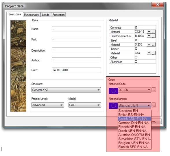
After clicking edit button (three dots button) next to combo box in the group National annex, dialogue Manager of National annexes is displayed (3.1.3)
Since SCIA Engineer version 2010, is default reinforcement material set directly in dialogue Project data. After checking concrete material check box, possibility to choose default concrete and reinforcement material is activated. Only one default common material is defined for all concrete members, in contrast to other codes where for each mentioned member must be separate default material defined in global settings. If we want to change any material for some specific member, we need to define local setting somehow. We can do this by creating local setting (concrete member data).
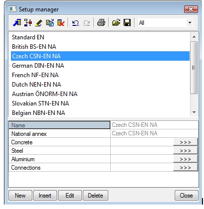
Since SCIA Engineer 2010 version, there is a new library called Setup manager. It can be accessed from:
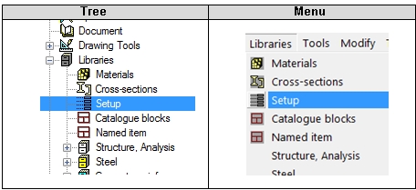
User can edit settings for all materials in Setup manager dialogue. Each country has predefined set of parameters. User is able to create own set of values with default values. He might also change the appearance and the number of items in settings. It is possible to work with the items as with items of other library, so user can edit, copy, save and load to/from file, etc. It is not possible to switch national annex here, this action can be done only in Project dialogue or in Manager of national annexes dialogue.
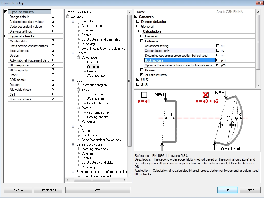
After clicking an edit button Concrete in Setup manager dialogue, dialogue Concrete setup appears. This dialogue displays all global parameters for concrete, without national annex parameters.
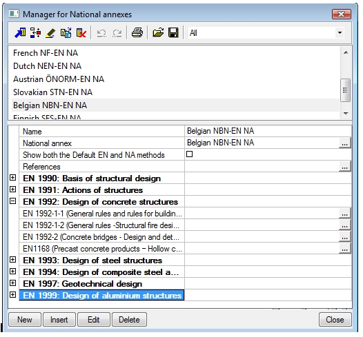
It is possible to edit national annexes parameters only by using this dialogue in SCIA Engineer. Manager of national annexes dialogue can be opened:

Dialogue Manager of National annexes is a library too. The library contains the same items as library Setup manager, because it is the same library and only different parameters are appeared in these libraries (different filters are used). The national parameters for selected national annex are sorted according to codes (for concrete there are implemented 4 codes).
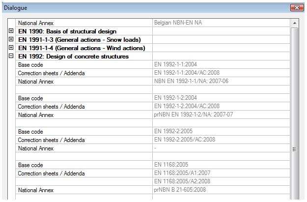
More detailed information (year of edition, correction sheets and addenda) about implemented codes and national annexes are appeared in the dialogue References ,which can be opened via button References.
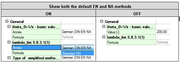
The useful feature is possibility for combination NA parameters from standard EN and from selected country. This possibility is allowed, if the check box Show both the default EN and NA methods in dialogue Manager of national annex is ON. If the check box is ON, then the user can select, if uses value/formula or methods from standard EN or from selected country. If the check box is OFF, only national parameters for selected country are available.
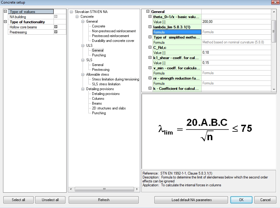
By pressing Edit button […] next to each code, dialogue with the national parameters defined in this code are appeared, for example in picture below is displayed dialogue with national parameters for code EN 1992-1-1 (General rules and rules for buildings).
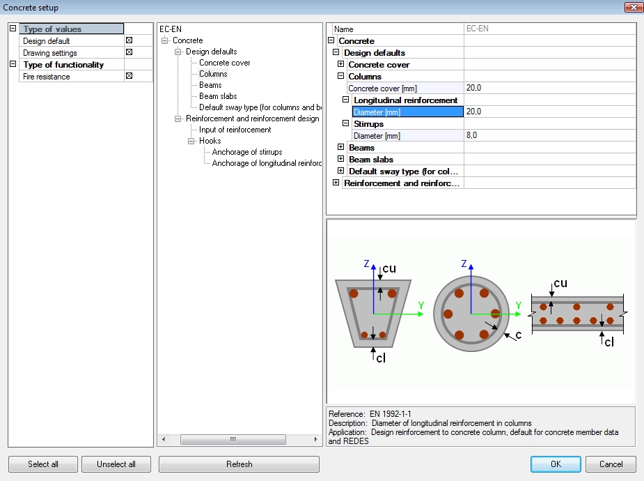
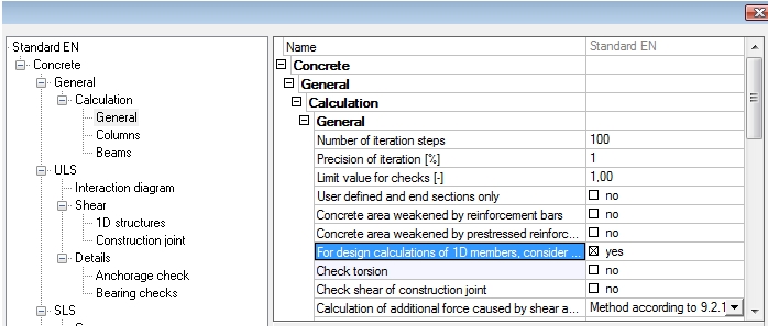
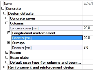
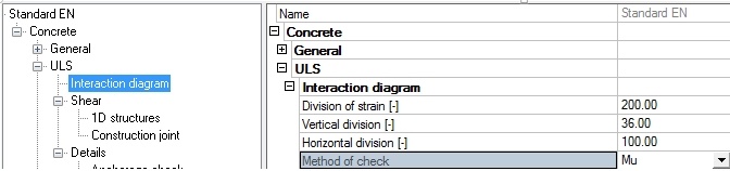
Code dependant values (except for national annexes parameters) and Code independent values, which have influence to design and check of concrete structures, are possible to edit in Concrete setup dialogue which can be displayed via Menu > Setup > Concrete solver.
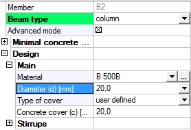
This is the first item in tree Concrete, and it is possible to set default values for member design (such as concrete cover, reinforcement diameters, direction angles, etc.), and also parameters for drawing of user reinforcement.
Global setting is adjustable via action button Concrete setup too, which is located in Properties window of all concrete services and in services for definition of local parameters.
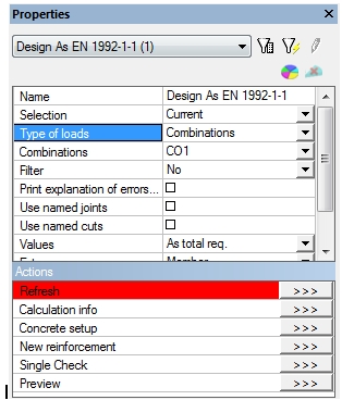
The main advantages of this action button dialogue are:
There are many parameters in global setting, which have influence on design and check of the columns:
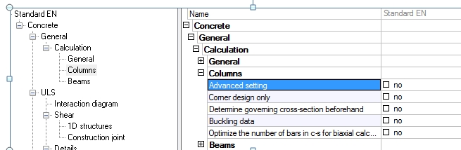
There are only 4 parameters in mode Basic setting, but after switching ON the check box Advanced setting, there are much more parameters for setting calculation of the columns.
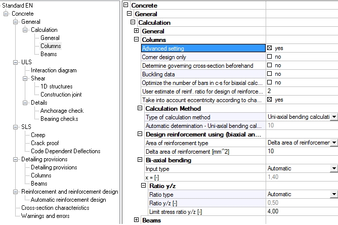
The most important parameters for design and check column will be described in the following chapters.
| Group | General > Calculation > General |
| Type of parameter | Check box |
| Default | OFF |
| Local setting | NO |
| Influence | Only design reinforcement |
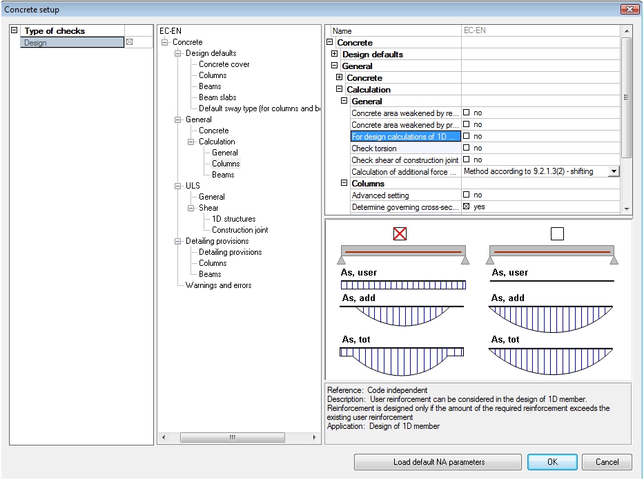
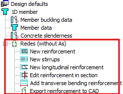
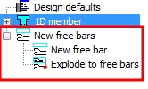
This parameter allows to taken into account user defined reinforcement. It means, if the check box is ON, then only additional reinforcement to existed user reinforcement will be designed. The user reinforcement in SCIA Engineer can be defined by three possibilities:
| Local setting | REDES | Free bars |
|
|
|
There are some limitations for design reinforcement to column, if the check box is ON:
| Group | General > Calculation > Columns |
| Type of parameter | Check box |
| Mode | Basic mode |
| Default | OFF |
| Local setting | YES |
| Influence | Only design reinforcement |
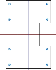
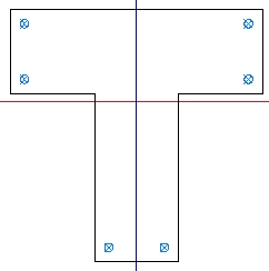
Corner design only is special type of calculation, where the reinforcement is designed only in corner of cross-section with internal angle 90 °. It is an iterative calculation, where number of bars is same, but the diameter of bars increases. This parameter has influence only for basic concrete cross-section, see table below.
| Section | Rectangular section | I section | T section | L section with lower flange | L section with upper flange |
| Number of bars | 4 | 8 | 6 | 5 | 5 |
| Shape | 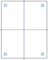
|
|
|
|
|
If this check box is ON, then for basic concrete cross-section the required reinforcement is designed, for other type of cross-section calculation finished with error 683 (The design of main reinforcement area for the column is not supported for this type of cross-section)
| Group |
General > Calculation > Columns |
| Type of parameter | Check box |
| Mode | Basic mode |
| Default | OFF |
| Local setting | NO |
| Influence | Only design reinforcement |
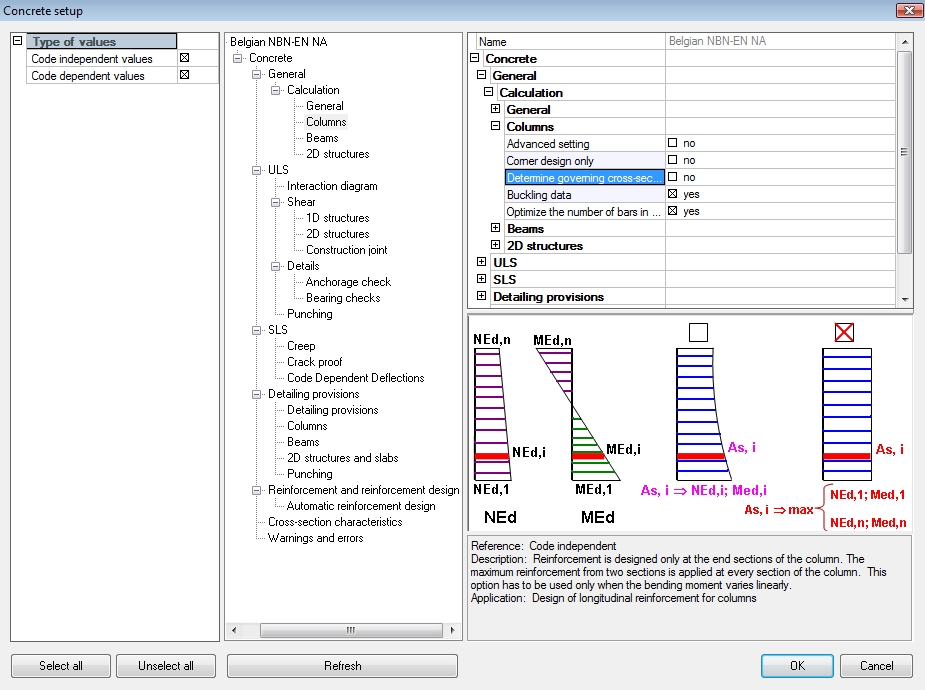
This setting allows to design reinforcement faster. There are two steps for design reinforcement to column for this setting.
It means that reinforcement is designed only in several sections, but it is checked in all sections. Since the check of reinforcement is faster than design of reinforcement, it follows that calculation can be faster with using this method. The speed of calculation depends on shape of bending line. The fastest calculation is for linear bending line, therefore this method is suitable for column without transverse load
1. The check box “Determine governing cross-section beforehand “ is not taken into account in single check in the service Member design-Design (tree Concrete Advanced > 1D member ), because there are evaluate result only for one section
2. The user reinforcement in the column is not taken into if check box “Determine governing cross-section beforehand “ is ON , because if the user reinforcement is defined, the area of reinforcement has not to be same at whole length of the column. The calculation finishes with error 882 ( It is not possible to use item Determine governing cross-section beforehand, because user reinforcement is input on the column)
| Group |
General > Calculation > Columns |
| Type of parameter | Check box |
| Mode | Basic mode |
| Default | ON |
| Local setting | YES |
| Influence | Design and ULS check |
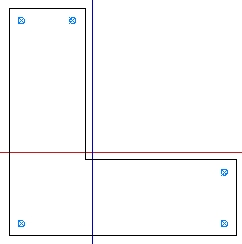
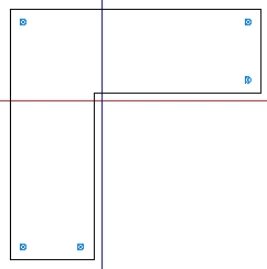
This setting allows to take into account second order eccentricity (method based on the nominal curvature) and eccentricity caused by imperfection. The second order eccentricity in direction of local axis will be taken into account only if slenderness of the column in this direction is greater than limit slenderness and this check box is ON. The eccentricity caused by imperfection will be taken into account always, if the check box is ON.
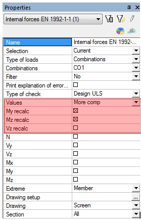
The value of second order eccentricity (e2) and eccentricity caused by imperfection (ei) are presented in numerical output in the service Internal forces (tree Concrete Advanced > 1D member), if the values My,recalc or Mz, recalc are selected.
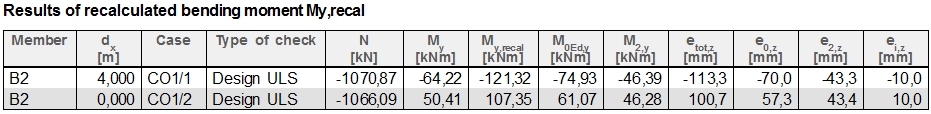
These eccentricity e2 and ei can be different for design and check reinforcement, because for design ratio of reinforcement sets in concrete setup (see chapter User estimate of reinf. for design of reinforcement ) is used and for check real user input reinforcement is taken into account. Therefore in service Internal forces (tree Concrete Advanced > 1D member) user can select which value will be presented via combo box Type of check.
| Group |
General > Calculation > Columns |
| Type of parameter | Check box |
| Mode | Basic mode |
| Default | ON |
| Local setting | NO |
| Influence | Only design reinforcement to column with rectangular section |
The design reinforcement with using biaxial methods depends on value Ratio y/z (ratio of reinforcement in direction of y and z of LCS), see chapter Group Ratio y/z. If this check box is ON, then the biaxial method is independent on value Ratio y/z and program tries to find the best arrangement of bars in cross-section with the minimum number of bars. It is iterative calculation, where program checked all possible arrangements of bars of reinforcement according to interaction formula (see chapter Group Biaxial bending ) and select this one, which result of interaction formula is the nearest to one.
This setting has influence to speed of calculation, because if the check box is ON, iterative calculation is used and therefore the speed of calculation is lesser, but the result of design in many cases is better, see table below
| Check box Optimize…is OFF | 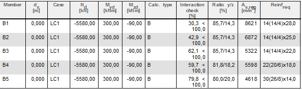
|
| heck box Optimize…is OFF | 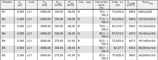
|
| Group |
General > Calculation > Columns |
| Type of parameter | Edit box |
| Mode | Advanced mode only |
| Default | 2% (Limit values from 0 to 10) |
| Local setting | NO |
| Influence | Only design reinforcement |
There are some values in design of reinforcement, which are dependent on area of reinforcement, for example:
These values should be calculated before design of reinforcement, but before design we do not know area of reinforcement. It follows that for calculation of this value
The third solution is implemented in SCIA Engineer via edit box User estimate of reinf. for design of reinforcement, where user can set ratio of reinforcement, which will be used for calculation of the values above. Total area of reinforcement is calculated according to formula:
As = Ratiolon.Ac
where Ac is area of cross-section
Ratiolon is ratio of reinforcement
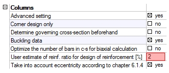
• If required designed area is lesser than 80% of estimated area setting in concrete setup, program gives warning 270 (The percentage of additional reinforcement is lesser than 80% of user estimate ratio). In this case, the value of user estimate ratio in concrete setup should be increased
• If required designed area is greater than 120% of estimated area setting in concrete setup, program gives warning 270 (The percentage of additional reinforcement is greater than 120% of user estimate ratio). In this case, the value of user estimate ratio in concrete setup should be increased
• For calculation of limit slenderness and second order eccentricity for check of column, the area of user real reinforcement is used.
| Group |
General > Calculation > Columns |
| Type of parameter | Check box |
| Mode | Advanced mode only |
| Default | ON |
| Local setting | NO |
| Influence | Design and ULS check |
Minimum the first order eccentricity including effect of imperfection ( value e0,min,y(z)) according to clause 6.1(4) in EN 1992-1-1 is necessary to assume h/30 or b/30 (depending on direction of calculation), but not less than 20 mm. This clause will be taken into account only, if this check box is ON , it means that first order eccentricity including effect of imperfection is calculated according to formula
eo,y(z) = e1,y(z) + ei,y(z) > e0,min,y(z)
If the check box is OFF, the following formula is used for calculation first order eccentricity including effect of imperfection
eo,y(z) = e1,y(z) + ei,y(z)
where
e1,y(z) the 1st order eccentricity in direction of y (z) axis of LCS (see chapter Calculation first order eccentricity without effect of imperfection)
ei,y(z) is eccentricity caused by imperfection in direction of y (z) axis of LCS (see chapter Calculation eccentricity caused by imperfection)
This minimum first order eccentricity is taken into account, only if check box Use buckling data is ON, see chapter Buckling data.
There are two basic properties in this group:
| Group |
General > Calculation > Columns |
| Type of parameter | Combo box |
| Mode | Advanced mode only |
| Default | Automatic determination |
| Local setting | YES |
| Influence | Only design reinforcement to column with rectangular section |
There are supported only following cross-section for design reinforcement to column in SEN:
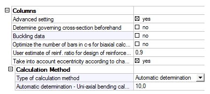
There are 4 methods for design reinforcement to column with the rectangular cross-section:
Type of method can be selected by user via combo box Type of calculation method.
• For design reinforcement to column with circular section the Biaxial calculation method is always used.
• For design reinforcement to column with T,I,L shape Only corner design can be used
| Group |
General > Calculation > Columns |
| Type of parameter | Edit box |
| Mode | Advanced mode only |
| Default | 10% (Limit values from 0 to 100) |
| Local setting | NO |
| Influence | Only design reinforcement to column with rectangular section |
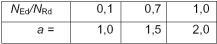
Type of calculation = automatic determination runs according to diagram below, where Um = Uniaxial bending calculation (max), Us = Uniaxial bending calculation (sum) and B = Biaxial bending calculation
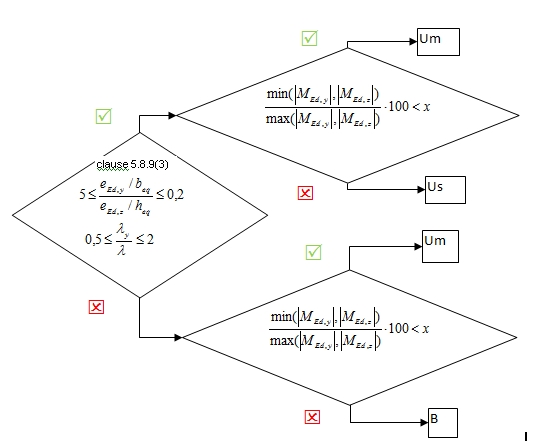
One condition in automatic determination type of calculation is ratio of biaxial bending moments, where limit value of this ratio (value x in diagram abobe) can be set in this edit box
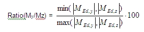
where
MEd,y is design value of the bending moment around y –axis including imperfection and second order effect
MEd,z is design value of the bending moment around z –axis including imperfection and second order effect
If this ratio is lesser than limit value set in this edit box, then for design of reinforcement in the section of the column Uniaxial bending calculation (max) will be used. Otherwise the Biaxial bending calculation or Uniaxial bending calculation (sum) will be used for design of reinforcement in depending on conditions in clause 5.8.9(3).
This edit box is active only in the case, if in the combo box Type of calculation method item Automatic determination is selected
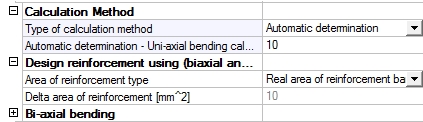
There are two basic properties in this group:
| Group |
General > Calculation > Columns |
| Type of parameter | Combo box |
| Mode | Advanced mode only |
| Default | Real area of reinforcement bar |
| Local setting | NO |
| Influence | Only design reinforcement to column for biaxial and only corner design |
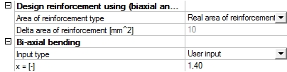
This combo box allows setting type of area of reinforcement for biaxial and only corner design, which will be used for design of reinforcement. There are two possibilities:
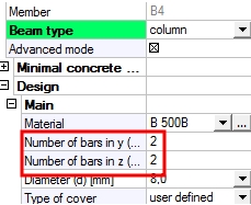
Concrete setup (Design default) Member data
| Concrete setup (Design default) |
Member data |
|
 |
• Delta are of reinforcement – the area of reinforcement set in edit box Delta area of reinforcement will add to cross-section instead of area real bars. It means, that resultant area of reinforcement is multiple of value Delta are of reinforcement, but number of bars is calculated for diameter of bars sets set in global setting (Concrete setup (Design default) of local setting (Member data). Use this option allows to make the more economical design of reinforcement, but it depends on value Delta area of reinforcement.
| Real area of reinforcement bars |
|
| Delta area of reinforcement (100 mm2) | 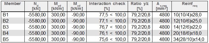
|
| Delta area of reinforcement (10 mm2) |
|
For method Only corner design the following principle are used
• For real area of reinforcement bars – the diameter of bar increases according to list of basic diameter, which can be different for each code. The initial value of diameter for calculation is loaded from concrete setup, item Design default or from concrete member data.
• For delta area of reinforcement – the diameter of bar is calculated from input value of delta area. The value delta area represents increasing area of one bar of reinforcement in each iteration step. The diameter of bars in each iteration step is calculated and it is rounded up to integer number.
| Group |
General > Calculation > Columns |
| Type of parameter | Edit box |
| Mode | Advanced mode only |
| Default | 10 mm2 (Limit values from 0 to 100000) |
| Local setting | NO |
| Influence | Only design reinforcement to column for biaxial and only corner design |
This edit box is used for inputting area of reinforcement, which will be used for biaxial and only corner design. It is active only, if item Delta area of reinforcement is selected from combo box Area of reinforcement type.
The interaction formula below is using for biaxial bending calculation
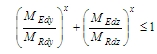
where
MEd,y is design value of the bending moment around y –axis including imperfection and second order effect
MEd,z is design value of the bending moment around z –axis including imperfection and second order effect
MRd,y is the moment resistance around y –axis calculated for the method Muy ()
MRd,z is the moment resistance around z –axis calculated for the method Muz
x Exponent of interaction formula
The group Biaxial bending allows to set value of exponent for interaction formula for rectangular column and there are two parameters:
The type of method (method Muy and Muz) for calculation moment of resistance can be set in Concrete solver (ULS > Interaction diagram >Method of check)
| Group |
General > Calculation > Columns |
| Type of parameter | Combo box |
| Mode | Advanced mode only |
| Default | Automatic |
| Local setting | NO |
| Influence | Only design reinforcement to rectangular column for biaxial bending calculation |
The user can select two methods for calculation exponent of interaction formula:
• The axial resistance NRd depends on area of longitudinal reinforcement, which is unknown value in procedure of design reinforcement, therefore the value NRd is calculated according to formula
NRd = Ac(fcd + Ratiolon∙fyd)
where:
Ac Cross-sectional area of concrete
fcd Design value of concrete compressive strength
Ratiolon Ratio of longitudinal reinforcement, see chapter User estimate of reinf. for design of reinforcement
fyd Design yield strength of reinforcement
• For design reinforcement to circular column, exponent x = 2 is used in interaction formula
| Group |
General > Calculation > Columns |
| Type of parameter | Edit box |
| Mode | Advanced mode only |
| Default | 1,4 (Limit values from 0 to 10) |
| Local setting | NO |
| Influence | Only design reinforcement to rectangular column for biaxial bending calculation |
The parameter x allows to set exponent for interaction formula directly by user. This parameter is active only, if Input type = User input.
The one of the most important parameter for biaxial bending calculation is ratio of reinforcement in y and z direction. There are three parameters which have influence to the ratio of the reinforcement
| Group |
General > Calculation > Columns |
| Type of parameter | Combo box |
| Mode | Advanced mode only |
| Default | Automatic |
| Local setting | YES |
| Influence | Only design reinforcement to rectangular column for biaxial bending calculation |
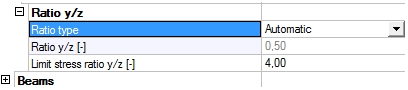
There are three possibilities for calculation ratio of reinforcement in biaxial bending calculation:
• Automatic - The value ratio y/z is calculated automatically as ratio of bending stresses in both direction
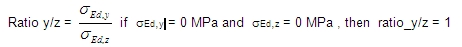
where
sEd,y the bending stress around y-axis, sEd,y = MEd,y/Wc,B,y
sEd,z the bending stress around y-axis, sEd,z = MEd,z/Wc,B,z
MEd,y(z) is design value of the bending moment around y(z) axis of LCS including imperfection and second order effect
Wc,B,y(z) section modulus for biaxial calculation around y (z) axis calculated for concrete cross-section without concrete cover
MEd,y(z) is design value of the bending moment around y(z) axis of LCS including imperfection and second order effect
Wc,B,y(z) section modulus for biaxial calculation around y (z) axis calculated for concrete cross-section without concrete cover

b,h dimension of rectangular cross-section
cnom nominal concrete cover of the stirrup
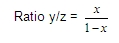
where
x Input value in parameter Ratio y/z
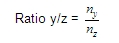
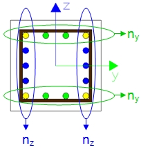
where
ny is number of bars in y direction of LCS including corner bars
nz is number of bars in z direction of LCS including corner bars
The user reinforcement can be defined:
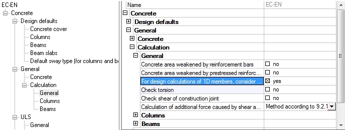
This option will be taken into account only if some user reinforcement is defined in the column and if the check box For design calculation of 1D member consider longitudinal user reinforcement (Concrete solver > General > Calculation > General ). If these conditions are not fulfilled, the ratio y/z will be calculated automatically (Ratio type = Automatic).
| Group |
General > Calculation > Columns |
| Type of parameter | Edit box |
| Mode | Advanced mode only |
| Default | 0,5 (Limit values from 0 to 10) |
| Local setting | YES |
| Influence | Only design reinforcement to rectangular column for biaxial bending calculation |
This edit box allows to input user value of ratio y/z. The ratio of reinforcement in y direction is input and the ratio in z direction is calculated by the program. This property is active, only if Ratio type = Manual.
| Group |
General > Calculation > Columns |
| Type of parameter | Edit box |
| Mode | Advanced mode only |
| Default | 4 (Limit values from 0 to 100) |
| Local setting | NO |
| Influence | Only design reinforcement to rectangular column for biaxial bending calculation |
Design reinforcement with using biaxial bending calculation depends on value ratio y/z (ratio of reinforcement in y/z ). If the ratio y/z is big, the program has to design many bars in one.
direction to interaction formula was fulfilled, but result of interaction formula is small. This solution is often uneconomical, therefore user can set limit ratio y/z via property Limit stress ratio (ratio y/z )lim). If ratio y/z > (ratio y/z )lim or ratio y/z < 1/(ratio y/z )lim ,then program gives warning 245 (An unusual design situation encountered: the stress ratio y/z exceeds the preset limit of the required reinforcement is hardly acceptable.Please, check the concrete setup) and user should:
– use different type of calculation (see chapter Group Calculation method) in global or in local setting
– switch on the check box Optimize the number of bars in c-s for biaxial calculation, see chapter Optimize the number of bars in c-s for biaxial calculation
– use different type of calculation for ratio y/z, see chapter Ratio y/z in global or in local setting
– use different type of reinforcement area, see chapter Group Design reinforcement using (biaxial and only corner design)
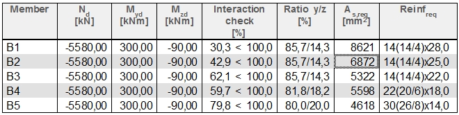
The possibility of correction calculation, when warning 245 is appeared, is presented in the table .
| Biaxial calculation, ratio type= Automatic, Optimalization=OFF, Real area of reinforcement bar | 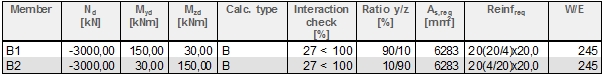
|
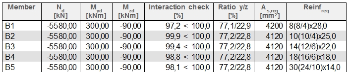
| Biaxial calculation, ratio type= Automatic, Optimalization=ON, Real area of reinforcement bar | 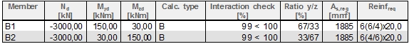
|
| Uniaxial calculation, ratio type= Automatic, Optimalization=OFF, Real area of reinforcement bar | 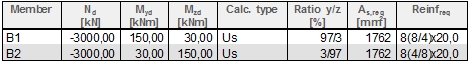
|
| Uniaxial calculation, ratio type= Manual, ratio y/z = 0,5, Optimalization=OFF, Real area of reinforcement bar | 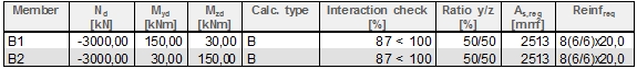
|
| InfluencBiaxial calculation, ratio type= Automatic, Optimalization=OFF, Delta area of reinforcement bar, delta = 10mm2 | 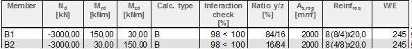
|