![]()
|
||
|
|
||
The calculation of first order moment runs according to the following procedure:
The first order eccentricity without effect of imperfection is calculated according to formulas below
where
e1,y(z) the 1st order eccentricity in direction of y (z) axis of LCS
M0Ed,y(z) the 1st order moment around of y (z) axis of LCS (in SCIA Engineer value My(z))
NEd the design axial force in calculated section of the column (in SCIA Engineer value N)
e0e,y(z) the 1st order equivalent eccentricity in direction of y (z) axis of LCS
M0e,y(z) the 1st order equivalent moment around of y (z) axis of LCS
N0,e the equivalent axial force
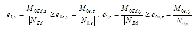
The 1st order equivalent moment is calculated according to clause 5.8.8.2 (2) in EN 1992-1-1
M0,ey = max (0,6*M02,y +0,4*M01,y; 0,4* M02,y)
M0,ez = max (0,6*M02,z +0,4*M01,z; 0,4*M02,z)
where
M01y(z) is first end bending moments around y(z) axis of LCS with lesser absolute value as second end bending moment. |M01y(z)|< |M02y(z)| The same values are used for calculation limit slenderness
M02y(z) is second end bending moments around y(z) axis of LCS with greater absolute value as first end bending moment. |M02y(z)|≥ |M01y(z)| The same values are used for calculation limit slenderness
The equivalent axial force is calculated according to same rules as equivalent bending moments
N0,e = max (0,6*N02 +0,4*N01; 0,4*N02)
where
N01 It is first end axial force with lesser absolute value as second end axial force. |N01|< |N02|.
N02 It is second end axial force with greater absolute value as first end axial force. |N01|< |N02|.
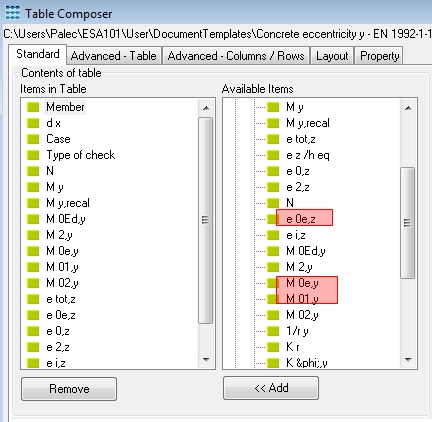
The equivalent values of bending moment and axial force are the same for all sections in column and the values of equivalent eccentricity and equivalent bending moments can be presented in numerical output after adding the selected values to table (via icon Table composer  in Preview)
The imperfection in SCIA Engineer is represented by an inclination according to clause 5.2(5) in EN 1992-1-1. The inclination is calculated around both axis ( axis y and z) of LCS according to formula:
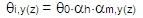
where
F0 is the basic value of inclination. The value is National parameter, it means that value can be different for each country. The value can be set in Concrete setup ( Manager for national annex > EN 1992-1-1 > General > ULS > General > Theta_0 )
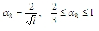
αh is the reduction factor for length of column or height of structure. The value is calculated according to formula
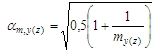
αm,y(z) is the reduction factor for numbers of members calculated according to formula
l is length of column or height of structure defined via parameter Tot.height in tab-sheet Buckling data in dialogue Buckling and relative lengths (member properties > parameter Buckling and relative length > button Edit ), see chapter 4.3
my(mz) is the number of vertical members contributing to the total effect of the imperfection perpendicular to y(z) of LCS. It means, that value is used for recalculation of bending moment around y(z) axis of LCS. These value can be defined in tab-sheet Buckling data in dialogue Buckling and relative lengths (member properties > parameter Buckling and relative length > button Edit )
The effect of imperfection for isolated column and for structure too is taken into account always as an eccentricity according to clause 5.2(7a) in EN 1992-1-1. At first step basic eccentricity caused by imperfection in both direction of local axis are calculated according to formula
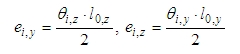
where
Fi,y(z) is the inclination around y(z) axis of LCS (perpendicular to y (z) axis of LCS)
l0,y(z) is the effective length of the member (column) around y(z) axis of LCS (perpendicular to y (z) axis of LCS), which can be defined via Member buckling data
In second step basic value of eccentricity caused by imperfection around of both local axis are recalculated depending on slenderness and first order eccentricities:
 otherwise
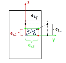
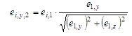
- in direction of z-axis
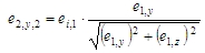
ei,y,2 = ei,z .... if e1,y=0otherwise
where
e1,y(z) is the 1st order eccentricity in direction of y (z) axis of LCS (see chapter Calculation first order eccentricity without effect of imperfection)
ei,1 is eccentricity caused by imperfection recalculated to direction of resultant first order eccentricity ei,1 = ei,y*cos(α)+ ei,z*sin(α). For simplification in SCIA Engineer the value ei,1 is calculated according to formula: ei,1 = max(ei,y;ei,z)
α is angle between direction of resultant first order eccentricity and y-axis of LCS
The final value of eccentricity caused by imperfection is calculated according to formulas below and these values are presented in numerical output for value
My,recal and Mz,recal
ei,y = max(ei,y,1; ei,y,2)
ei,z = max(ei,z,1; ei,z,2)
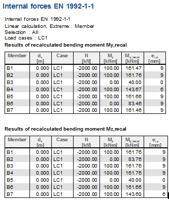
The table of recalculated and final eccentricity caused by imperfection for different values of slenderness and first order eccentricities according to inputted values and previous formulas is below (example Tutorial_column_02.esa)
| Type | Column | B1 | B2 | B3 | B4 | B5 | B6 | B7 |
| Basic | ei,y [mm] | 9 | 9 | 9 | 9 | 9 | 9 | 9 |
| ei,z [mm] | 9 | 9 | 9 | 9 | 9 | 9 | 9 | |
| e1,y [mm] | 50 | 0 | 50 | 50 | 0 | 50 | 50 | |
| e1,z [mm] | 50 | 50 | 0 | 50 | 50 | 0 | 50 | |
| slenderness | ly = lz | ly < lz | ly < lz | ly < lz | ly > lz | ly > lz |
ly > lz |
|
| Recalculated | ei,y,1 [mm] | 9 | 9 | 9 | 9 | 0 | 0 | 0 |
| ei,z,1 [mm] | 9 | 0 | 0 | 0 | 9 | 9 | 9 | |
| ei,y,2 [mm] | 9 | 0 | 9 | 6 | 0 | 9 | 6 | |
| ei,z,2 [mm] | 9 | 9 | 0 | 6 | 9 | 0 | 6 | |
| Final | ei,y [mm] | 9 | 9 | 9 | 9 | 0 | 9 | 6 |
| ei,z [mm] | 9 | 9 | 0 | 6 | 9 | 9 | 9 |
The results in SCIA Engineer are the following:
The direction (sign) of final value of eccentricity caused by imperfection has to be same as direction (sign) of first order eccentricity.
First order eccentricity including effect of imperfection is calculated according to formula below
eo,y(z) = e1,y(z) + ei,y(z) > e0,min,y(z)
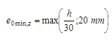
The minimum first order eccentricity similar as eccentricity caused by imperfection is calculated in direction of both local axis according to formulas below:
where
e1,y(z) Is the 1st order eccentricity in direction of y (z) axis of LCS (see chapter Calculation first order eccentricity without effect of imperfection)
ei,y(z) is eccentricity caused by imperfection in direction of y (z) axis of LCS (see chapter Calculation eccentricity caused by imperfection)
e0,min,y(z) is minimum first order eccentricity in direction of y (z) axis of LCS according to clause 6.1(4) in EN 1992-1-1. This minimum value will be taken into account only in case, that check box Take into account eccentricity according to chapter 6.1.4 is ON (Concrete solver >General > Calculation > Columns >Advanced mode), see chapter Take into account eccentricity according to chapter 6.1.4
b is maximum width of cross-section (maximum dimension of cross-section in direction of y axis of LCS)
h is height of the cross-section ( dimension of cross-section in direction of z axis of LCS))
After calculation of first order eccentricity including effect of imperfection, the 1st order moment, including the effect of imperfections around y (z) axis of LCS is calculated:
M0Ed,y(z) = NEd* eo,z(y)
The table of recalculated and final second order eccentricities for different value of first order eccentricities according to inputted values and previous formulas is below (example Tutorial_column_03.esa)
| Type |
Column b/h =400/700 mm |
B1 (x=0) |
B1 (x=1.8) |
B2 (x=0) |
B2 (x=1.8) |
B3 (x=0) |
B3 (x=1.8) |
| Basic | M0Ed,z/NEd [mm] | -50 | 0 | 0 | 0 | -50 | 0 |
| M0Ed,y/NEd [mm] | -50 | 0 | -50 | 0 | 0 | 0 | |
| e0e,y[mm] | 20 | 0 | 20 | ||||
| e0e,z[mm] | 20 | 20 | 0 | ||||
| e1,y [mm] | -50 | 20 | 0 | 0 | -50 | 20 | |
| e1,z [mm] | -50 | 20 | -50 | 20 | 0 | 0 | |
| Recalculated | ei,y [mm] | -9 | 9 | 9 | 9 | -9 | 9 |
| ei,z [mm] | -6 | 6 | -9 | 9 | 0 | 0 | |
| e0,min,y [mm] | -20 | 20 | 20 | 20 | -20 | 20 | |
| e0,min,z [mm] | -23 | 23 | -23 | 23 | 23 | 23 | |
| Final | e0,y [mm] | -59 | 29 | 20 | 20 | -59 | 29 |
| e0,z [mm] | -56 | 26 | -59 | 29 | 23 | 23 | |
The results in SCIA Engineer are the following:
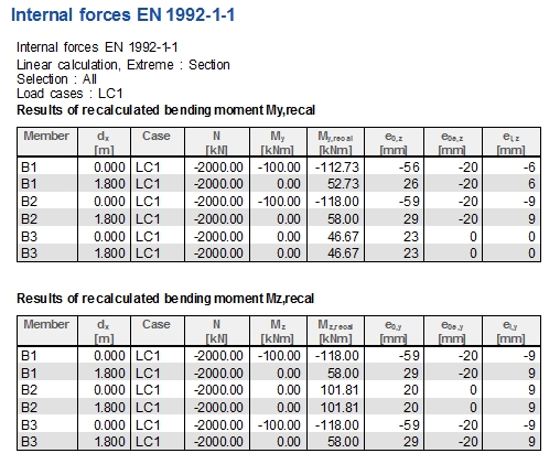
• First order moment and eccentricity including effect of imperfection are presented in numerical output for value My recal and Mz recal
• The direction (sign) of minimum first order eccentricity has to be same as direction (sign) of first order eccentricity
Nominal second order moment is calculated according to clause 5.8.8.2(3) in EN 1992-1-1
M2,y(z) = NEd* e2,z(y)
where
NEd is the design axial force in calculated section of the column (in SCIA Engineer value N)
e2,z(y) is the second order eccentricity in direction of z (y) axis of LCS
The basic value of second order eccentricity is taken into account only if:
The basic values of second order eccentricity are calculated according to formulas below in first step:
| lz >lz,lim | check box Use buckling data | Second order eccentricity |
| YES | ON | e2,y = (1/r)z.l0,z2 / cz |
| YES | OFF | e2,y = 0 |
| NO | ON | |
| NO | OFF | |
| ly >ly,lim | check box Use buckling data | Second order eccentricity |
| YES | ON | e2,z = (1/r)y.l0,y2 / cy |
| YES | OFF | e2,z = 0 |
| NO | ON | |
| NO | OFF |
where
(1/r)y(z) is the curvature around y(z) axis of LCS (perpendicular to y (z) axis of LCS) calculated according to clause 5.8.8.3 in EN 1992-1-1
l0,y(z) is the effective length of the member (column) around y(z) axis of LCS (perpendicular to y (z) axis of LCS), which can be defined via Member buckling data
cy(z) is a factor depending on the curvature distribution around y(z) axis of LCS according to clause 5.8.8.2(4) in EN 1992-1-1.
cy(z) = 8 (for constant first order bending moment at whole length of the column around y(z) axis of LCS)
cy(z) = 10 (for the other cases)
ly(z) Slenderness ratio around y(z) axis of LCS
ly(z),lim Limit slenderness ratio around y(z) axis of LCS
In second step basic value of second order eccentricities in direction of both local axis are recalculated depending on slenderness and first order eccentricities
- in direction of z-axis
e2,z,1 = e2,z .... if ly ≤ lz
e2,z,1 = 0m .... if ly > lz
 otherwise
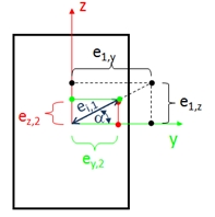
- in direction of z-axis
e2,z,2 = e2,z .... if e1,y=0otherwise
where
e1,y(z) is the 1st order eccentricity in direction of y (z) axis of LCS (see chapter Calculation first order eccentricity without effect of imperfection)
ei,1 is second order eccentricity recalculated to direction of resultant first order eccentricity ei,1 = e2,y•cos(α)+ e2,z•sin(α). For simplification in SCIA Engineer the value ei,1 is calculated according to formula: ei,1 = max(e2,y;e2,z)
α is angle between direction of resultant first order eccentricity and y-axis of LCS
The final value of eccentricity caused by imperfection is calculated according to formulas below and these values are presented in numerical output for value My,recal and Mz,recal
e2,y = max(e2,y,1; e2,y,2)
e2,z = max(e2,z,1; e2,z,2)
The table of recalculated and final second order eccentricities for different value of slenderness and first order eccentricities according to inputted values and previous formulas is below (example Tutorial_column_02.esa)
| Type | Column | B1 | B2 | B3 | B4 | B5 | B6 | B7 |
| Basic | e2,y [mm] | 22 | 22 | 22 | 22 | 22 | 22 | 22 |
| e2,z [mm] | 22 | 22 | 22 | 22 | 22 | 22 | 22 | |
| e1,y [mm] | 50 | 0 | 50 | 50 | 0 | 50 | 50 | |
| e1,z [mm] | 50 | 50 | 0 | 50 | 50 | 0 | 50 | |
| slenderness | ly = lz | ly < lz | ly < lz | ly < lz | ly > lz | ly > lz |
ly > lz |
|
| Recalculated | e2,y,1 [mm] | 22 | 22 | 22 | 22 | 0 | 0 | 0 |
| e2,z,1 [mm] | 22 | 0 | 0 | 0 | 22 | 22 | 22 | |
| e2,y,2 [mm] | 22 | 0 | 22 | 15 | 0 | 22 | 15 | |
| e2,z,2 [mm] | 22 | 22 | 0 | 15 | 22 | 0 | 15 | |
| Final | e2,y [mm] | 22 | 22 | 22 | 22 | 0 | 22 | 15 |
| e2,z [mm] | 22 | 22 | 0 | 15 | 22 | 22 | 22 |
The results in SCIA Engineer are the following:
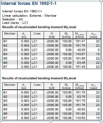
The direction (sign) of final value of second order eccentricity has to be same as direction (sign) of first order eccentricity
The curvature for calculation of second order eccentricity is calculated according to clause 5.8.8.3 in EN 1992-1-1.
(1/r)y(z) = Kr*Kf,y(z)*(1/r0)y(z)
where
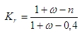
Kr is a correction factor depending on axial load, see clause 5.8.8.3 (3) in EN 1992-1-1. This factor depends on relative normal force (n) and mechanical ratio of reinforcement (ω).
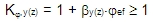
Kf,y(z) is factor for taking into account of creep around y(z) axis of LCS , see clause 5.8.8.3 (4) in EN 1992-1-1. This factor depends on effective creep ratio (φef) and factor (βy(z)) depending on slenderness
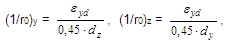
(1/r0)y(z) is the basic value of curvature around y(z) axis of LCS. This value depends on effective depth of cross-sections and strain in reinforcement at reaching design yield strength of reinforcement
It follows that the calculation of curvature depends on many parameters and factors, but the most important are the following:
Relative normal force
Relative normal force is used for calculation correction factor Kr and it is calculated according to formula
n = NEd / Ac•fcd
where
NEd is design value of the applied axial force in compression in calculated sections
Ac is cross sectional area of concrete
fcd is design value of concrete compressive strength
Mechanical reinforcement ratio
Mechanical reinforcement ratio, which is used for calculation correction factor Kr, depends on total area of longitudinal reinforcement. It follows that for design of reinforcement to column and for check of column different mechanical ratio can be taken into account.
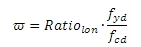
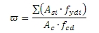
where
Ratiolon is reinforcement ratio loaded from concrete setup (Concrete solver >General > Calculation > column > Advanced setting > User estimate of reinf. for design of reinforcement), see chapter User estimate of reinf. for design of reinforcement
fyd is design yield strength of reinforcement. The quality of reinforcement can be input in Project data or in concrete member data (see chapter 4.2.34.2.4), if concrete member data is inputted on checked column
fcd is design value of concrete compressive strength
Asi is cross-sectional area of i-th reinforcement in the cross-section inputted via REDES or Free bars
fydi is design yield strength of i-th reinforcement in the cross-section inputted via REDES or Free bars inputted via REDES or Free bars
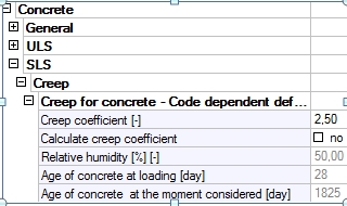
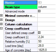
Effective creep ratio
In SCIA Engineer for calculation factor Kf,y(z) is used creep ratio loaded from concrete setup (if member data is not defined on column) or concrete member data. It means that if user wants to take into account effective creep ratio according to clause 5.8.4 in EN 1992-1-1, the value of this creep ratio has to be directly input to concrete setup or to concrete member data. Otherwise, the final creep ratio will be taken into account.
| Concrete solver > SLS > Creep | Concrete member data |
|
|
Slenderness
Slenderness of the column for calculation of factor Kf,y(z) is taken into account by parameter (by(z)) , which is calculated according to formula: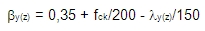
where
fck is characteristic value of concrete compressive strength
ly(z) is slenderness ratio around y(z) axis of LCS
Effective depth of cross-section
Effective depth of cross-section is used for calculation basic value of curvature and it is calculated according to clause 5.8.8.3(2) in EN 1992-1-1.
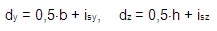
where
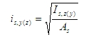
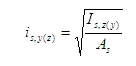
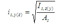
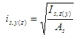
isy(z) is the radius of gyration of the total reinforcement area in direction of y(z) axis of LCS
b is maximum width of cross-section (maximum dimension of cross-section in direction of y axis of LCS)
h is height of the cross-section ( dimension of cross-section in direction of z axis of LCS))
The radius of gyration of the total reinforcement depends on selected item in combo box Type of check (tree Concrete Advanced > 1D member > Internal forces). It means, the radius of gyration of the total reinforcement can be different for design of reinforcement to column and for check of column. The calculation for design of reinforcement to column depends on type of method and shape of concrete cross-section too. There are the following methods for calculation the radius of gyration of the total reinforcement:
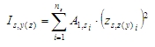
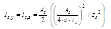
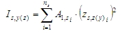
- second moment of reinforcement area
- radius of gyration of the total reinforcement area
 then
then 
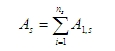
where
Ratiolon is reinforcement ratio loaded from concrete setup (Concrete solver >General > Calculation > column > Advanced setting > User estimate of reinf. for design of reinforcement), see chapter User estimate of reinf. for design of reinforcement
Ac is cross sectional area of concrete
ns is number of bars in cross-section (the number of bars for Only corner design depends on shape of cross-section, see chapter Corner design only)
A1si is the cross-sectional area of i-th bar of reinforcement
zs,y(z)i is the position of i-th bar of reinforcement from centroid of concrete cross-section in direction of y(z) axis of LCS (the positions of bars for Only corner design depends on shape of cross-section, see chapter Corner design only)
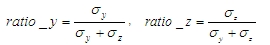
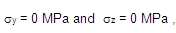
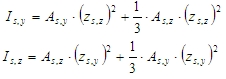
sy(z) is the bending stress in concrete calculated for uncracked concrete cross-section according to formulas: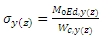
M0Ed,y(z) is the 1st order moment around of y (z) axis of LCS (in SEN value My(z)) without imperfection
Wc,y(z) is the section modulus of concrete cross-section around y (z) axis of LCS
zs,y(z) is the position of reinforcement from centroid of concrete cross-section in direction of y (z) axis for rectangular section (the positions of bars for Only corner design depends on shape of cross-section, see chapter Corner design only)
zs is th position of reinforcement from centroid of concrete cross- for circular section
b is width of rectangular cross-section
h is height of the rectangular cross-section
D is diameter of circular cross-section
cnom is nominal concrete cover loaded from concrete setup (Design default) or from concrete member data, if member data are defined on calculated column
ds is diameter of longitudinal reinforcement loaded from concrete setup (Design default) or from concrete member data, if member data are defined on calculated column
dss is diameter of transverse reinforcement (stirrup) loaded from concrete setup (Design default) or from concrete member data, if member data are defined on calculated column
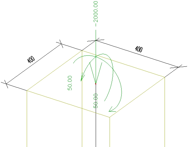
In the table below is calculation effective depth of cross-section for different type of check, different cross-section and different method
| cnom = 35 mm, ds = 20 mm, dss = 8 mm | ||
|
Type of check = Design ULS Only corner design = ON Cross-section = standard |
|
ns = 4; b = h = 0,4 m; Ac = 0,4·0,4 = 0,16 m2 Ratiolon = 2% = 0,02 As = 0,02·0,16 = 0,0032 m2; A1si=0,0032/4 = 0,0008 m2 zs,y = zs,z = 0,5· 0,4-(0,0350,008+0,5·0,02) = 0,147 m zs,y1 = zs,y3 = zs,y = 0,147 m; zs,y2 = zs,y4 = -zs,y = -0,147 m zs,z1 = zs,z2 = zs,z = 0,147 m; zs,z3 = zs,z4 = -zs,z = -0,147 m Isy = ΣAsi•zs,zi2 = 69,15·10-6 m4; Isz = ΣAsi•zs,yi2 = 69,15·10-6 m4 isy = isz = 0,147 m dy = dz = 0,5·0,4 + 0,147 = 0,347 m |
|
Type of check = Design ULS Only corner design = OFF Cross-section = rectangle |
|
b = h = 0,4 m; Ac = 0,4·0,4 = 0,16 m2 Ratiolon = 2% = 0,02; As = 0,02·0,16 = 0,0032 m2 M0Ed,y = -100 kNm, M0Ed,z = -100 kNm Wc,y = Wc,z = 0,4·0,42/6 = 0,01067 m3 σy = 100/0,01067 = 9,372 MPa; σz = 0/0,01067 = 0 MPa Ratio_y = 1, Ratio_z = 0 Asy = 1,0·0,0032 = 0,0032 m2, Asz = 0 m2 zs,y = zs,y = 0,5· 0,4-(0,035+0,008+0,5·0,02) = 0,147 m Isy = 69,15·10-6 m4; Isz = 23,05·10-6 m4 isy = 0, 085 m; isz = 0,147 m dy = 0,5·0,4+0,085 = 0,285 m; dz = 0,5·0,4+0,147 = 0,347 m |
|
Type of check = Design ULS Only corner design = OFF Cross-section = rectangle |
|
b = h = 0,4 m; Ac = 0,4·0,4 = 0,16 m2 Ratiolon = 2% = 0,02; As = 0,02·0,16 = 0,0032 m2 M0Ed,y = -100 kNm, M0Ed,z = -60 kNm Wc,y = Wc,z = 0,4·0,42/6 = 0,01067 m3 σy = -100/0,01067 = -9,37 MPa; σz = -60/0,01067 = -5,62 MPa Ratio_y = 0,625, Ratio_z = 0,375 Asy = 0,625·0,0032 = 0,002 m2; Asz = 0,375·0,0012 = 0,0012 m2 zs,y = zs,z = 0,5· 0,4-(0,035+0,008+0,5·0,02) = 0,147 m Isy = 51,86·10-6 m4; Isz = 40,33·10-6 m4 isy = 0,112 m, isz = 0,127 m dy = 0,5·0,4+0,112 = 0,312 m; dz = 0,5·0,4+0,127= 0,327 m |
|
Type of check = Design ULS Only corner design = OFF Cross-section = circular |
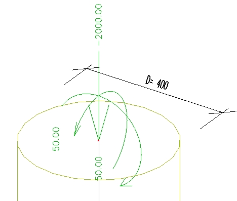
|
D =0,4 m; Ac = 0,25•π•D2= 0,126 m2 Ratiolon = 2% = 0,02; As = 0,02·0,126 = 0,0025 m2 zs = 0,5· 0,4-(0,035+0,008+0,5·0,02) = 0,147 m Isy = Isz=27,15·10-6 m4 isy = isz = 0,104 m dy = dz = 0,5·0,4 + 0,104 = 0,304 m |
|
Type of check = Non-prestressed ULS checks Only corner design = OFF Cross-section = all |
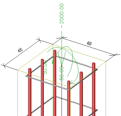
|
b = h = 0,4 m; Ac = 0,4·0,4 = 0,16 m2 Reinforcement = 6ϕ20 (B400B); ns = 6 A1si = 0,000314 m2 ; As = 6• 0,000314 = 0,00188 m2 zs,y = zs,z = 0,5· 0,4-(0,035+0,008+0,5·0,02) = 0,147 m zs,y1 = zs,y4 = zs,y = 0,147 m; zs,y3 = zs,y6 = -zs,y = -0,147 m zs,y2 = zs,y4 = 0 m; zs,z1 = zs,z2 = zs,z3 = zs,z = 0,147 m; zs,z4 = zs,z5 = zs,z6 = -zs,z = -0,147 m Isy = ΣAsi•zs,zi2 = 40,71·10-6 m4; Isz= ΣAsi•zs,yi2= 27,14·10-6 m4 isy = 0,120 m; isz = 0,147 m dy = 0,5·0,4 + 0,120 = 0,320 m; dy = 0,5·0,4 + 0,14 = 0,347 m |
The user (real) reinforcement defined via REDES and free bars are not taken into account for calculation effective depth of cross-section for design reinforcement to column (Type of check = Design ULS in service Internal forces)
Calculation of strain in reinforcement at reaching design yield strength of reinforcement
Strain in reinforcement at reaching design yield strength of reinforcement is used for calculation basic value of curvature. This value depends on material properties of reinforcement. It follows that for design of reinforcement to column and for check of column different value can be taken into account.

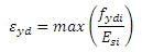
where
fyd is design yield strength of reinforcement. The quality of reinforcement can be input in Project data or in concrete member data (see chapter Group Design and Group Column calculation), if concrete member data is inputted on checked column
Es is design value of modulus of elasticity of reinforcement. The quality of reinforcement can be input in Project data or in concrete member data (see chapter Group Design and Group Column calculation), if concrete member data is inputted on checked column
fydi is design yield strength of i-th reinforcement in the cross-section inputted via REDES or Free bars inputted via REDES or Free bars
Esi is design value of modulus of elasticity of i-th reinforcement in the cross-section inputted via REDES or Free bars inputted via REDES or Free bars