![]()
|
||
|
|
||
Since version 14.1 it is possible to display displacements also on surfaces of 2D members
The new result 3D displacement for checking the displacements of the structure is available in version 14.
The major possibilities of this result are:
Available magnitudes which can be displayed are:
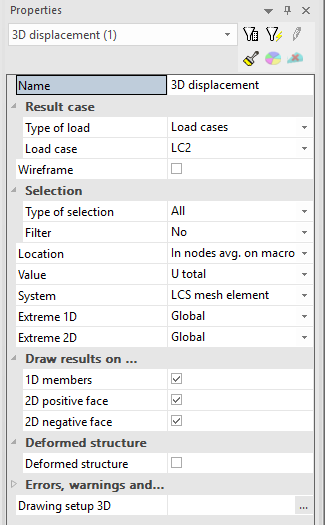
The property group Result case enables to specify the loading conditions for which the result is calculated. it enables to select from available Types of load (Load case, Combination, Nonlinear combination, Result class, ...) and then the particular instance for selected Type of load.
For envelope combinations or for result classes it is possible to switch between maximal or minimal values. This selection influences the values displayed as isolines. In each node of the isolines the maximum or minimum is taken as the result value.
Wireframe check box turns ON that only centre lines and centre planes are used for calculation and displaying the results. This option is much less demanding on performance resulting to faster visualization of the results and deformed shape of structure.
The group selection enables to modify the range of entities where the results are displayed. It is possible to combine available selection types with filters. The final range of entities is the intersection of selection and the filter.
User can select between available magnitudes which are described above.
The selected values is also used as the primary magnitude in the output tables. The extremes are searched for this selected value.
Setting of Extreme is respected in the tabular output only. The extreme setting for the graphical output is inside the Drawing setup 2D.
The displacement of particular fibres U are influenced also by rotation of sections. Therefore there are e.g. non zero displacements caused by the pure torsion:
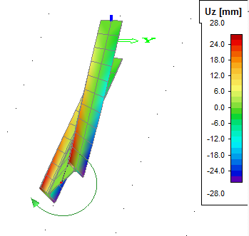
The displacements are calculated using the small displacement assumption. The translations of particular fibres caused by the rotation of sections are linear.
The rotation j causes translation of point "0" to the point "2":
![]()
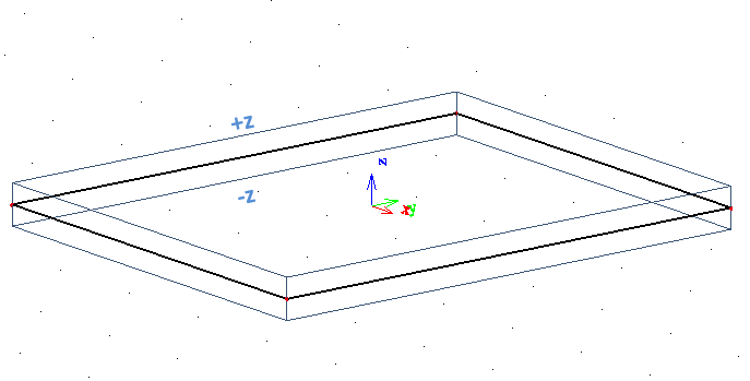
It is possible to switch ON/OFF drawing of results on 1D members or faces of 2D members.
Positive face is the face which is on +z local coordinate of the 2D member, negative face is on -z local coordinate of the 2D member.
The result values can be displayed also on deformed surface of the structure.
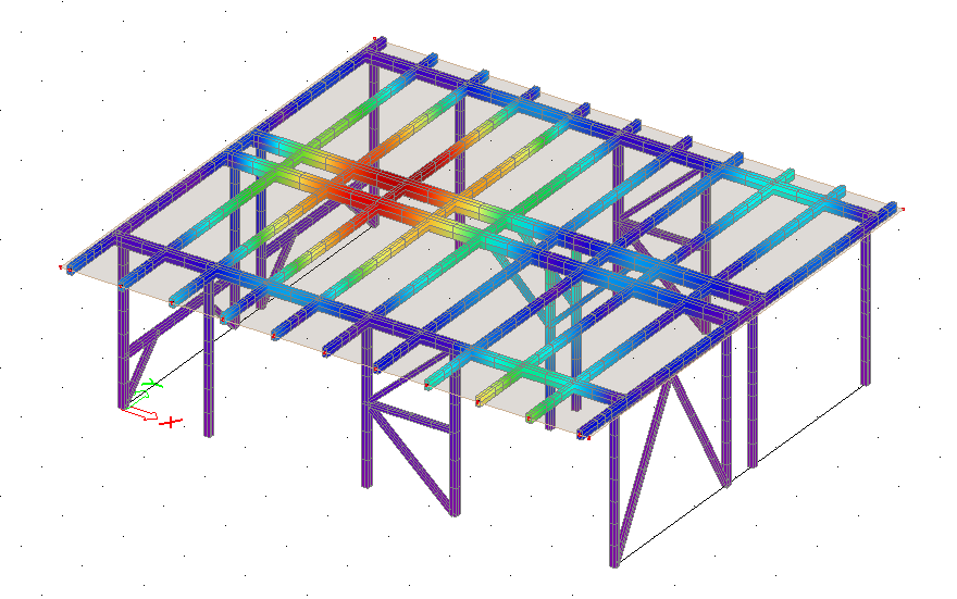
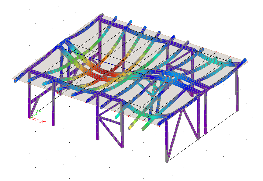
The deformed surface is displayed for the combination from selected result case which provides the extreme value of selected magnitude. In case the result type contains envelope combination (different combinations can give extreme values for each member of the structure) it is possible to select between "Member deformation for global / local maximum".
The checkbox "For drawing use linear rotation" enables to switch between small displacement assumption based linear translations (which provides result consistent with used assumption) and circular translations (which keeps the original shape of cross section).
![]()
![]()