Composite Deck Analysis Model - Theoretical background
This chapter gives a detailed description of the calculation of the orthotropic properties of composite and metal decks in SCIA Engineer. For an overview, see the chapter related to the Composite Analysis Model.
General principles
In the context of the CAM, the deck is the plate that carries the loads and transfers them to the beams. This section describes the principle of analysis of that plate only. The behaviour of composite beams will be discussed in another section.
The principle described here for the analysis of the deck is used directly when the deck is analyzed as a FE plate, as well as for the in-plane stiffness in the case of a semi-rigid diaphragm. In the case of rigid and flexible diaphragms, the real stiffness of the deck is not taken into account. However, in all cases, the orthotropic properties of the deck are taken into account when determining the influence of the participating width in the modified properties of the cross-section of composite beams.
There are composite decks and metal decks. A composite deck has two layers: a profiled steel sheeting and a concrete topping, reinforced or not. A metal deck has only one layer, i.e. the profiled steel sheeting, and is mostly used for light-weight roofs.
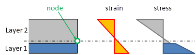
A composite deck is modelled as a multi-layered plate. Each layer has orthotropic properties and the eccentricity of each layer is taken into account.
The interaction of the layers is considered as a perfect bond, i.e. without any slip between the layers (concrete and steel sheeting). The strains are determined from the displacements and rotations at the nodes of the finite element mesh.
The assumption of perfect bond is reasonable for the longitudinal behaviour of the composite deck, i.e. in the direction parallel to the corrugation. In the direction perpendicular to the corrugation, this seems less obvious, since the profiled sheeting properties are first determined independently. In the composite deck, the “accordion” behaviour of the sheeting will be stabilized by the concrete in case the sheeting is in compression. However, the stiffness of the sheeting in that direction is very low and will hardly influence the behaviour of the composite deck. That approximation is therefore acceptable.
Please note, that the concrete-steel bond applies only in final stage. In construction stage, only the stiffness of the steel sheeting is taken into account (see Construction stages for composite analysis below).
Profiled steel sheeting
Es, Gs, νs = Young’s modulus, shear modulus and Poisson’s ratio of steel
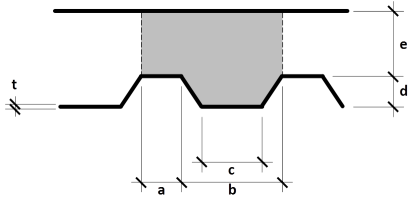
a, b, c, d, t define the geometry of the profiled sheeting; e is the thickness of the concrete topping and is not used in this context.
The formulas below give the components of the equivalent orthotropic properties of a generic profiled steel sheeting as shown in the above picture. Formulas adapted from Samanta & Mukopadhyay [1, 2].

Bending components


Membrane components


Mean thickness (for calculation of self weight)

Position of gravity centre from bottom fibre (assumed for both directions)

Auxiliary variables
|
|
|
|
|
|
|
|


Concrete deck
Ec, Gc, νc= Young’s modulus, shear modulus and Poisson’s ratio of concrete
a, b, c, d, e define the geometry of the concrete deck.
The formulas below give the components of the equivalent orthotropic properties of the concrete topping cast onto a generic profiled steel sheeting as shown in the above picture. Formulas adapted from Samanta & Mukopadhyay [1, 2].
Bending components


Membrane components


Mean thickness (for calculation of self weight)

Position of gravity centre from bottom fibre (assumed for both directions)

Auxiliary variables
|
|
|
|
|
|
|
|
|
|
|
|
|
|
||


Multi-layered orthotropy
The orthotropy sub-matrices are obtained from the formulas in the previous paragraphs. For each layer, there are:

where i is the layer index; in the case of a composite deck, s (steel) or c (concrete).
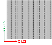
Proper rotation of the matrices must be applied before combining the layers, in case the orientation of the steel sheeting does not correspond to the default coordinate system. The rotation matrices are


where

 is the angle between the principal orthotropy direction Y’ (corrugation of the steel sheeting) and the default (non rotated) local Y axis of the 2D member. In SCIA Engineer, it is given by the LCS rotation angle in the 2D member properties.
The rotated orthotropy sub-matrices, for each layer, are

Finally, the layers must be combined and the eccentricity terms added in the matrix. The final orthotropy matrix has the form

Plate behaviour components (bending and shear)


Membrane behaviour components

Layer eccentricities

where zi is the position of the gravity centre of the i-th layer (profiled sheeting or concrete).
Because of the effect of creep, the value of Ec varies depending on the considered stage (construction, final long term, final short term). Therefore, the matrices must be computed separately for each stage.
One-way decks
It is a common assumption to consider composite decks and metal decks as one-way plates. In the case of an orthotropic plate, implementing such a behaviour also helps reducing "disturbances" due to the two-way behaviour, as that typically produces results that are very different from hand calculation and are hence difficult to validate intuitively.
The one-way behaviour is introduced in the combined orthotropy matrix by reducing the bending stiffness components in the non-supporting direction, i.e. dividing the corresponding components by a reduction coefficient, kone.
It is important to note, however, that the correction must be applied to the combined matrix - not to the individual layers. In order to do that, the relevant sub-matrix must be extracted before applying the correction. This is done in several steps, as follows:
1. Extract sub-matrices from the resulting orthotropy matrix

2. Calculate the resulting eccentricity for each component of the matrix


3. Calculate the bending stiffness due to the eccentricity of the membrane components

4. Calculate the pure bending part of the bending components

5. Backward rotation, back to the original axes of the steel sheeting


Note: the rotation matrices are the same as defined before in the Multi-layered orthotropy section.
6. Apply the stiffness reduction coefficient


7. Forward rotation, to the final orientation of the 2D member


Note: the rotation matrices are the same as defined before in the Multi-layered orthotropy section.
8. Re-inject the eccentric part of the bending stiffness (calculated in step 3)

9. Re-combine the orthotropy matrix

Important: some correction must also be applied in the calculation of the stiffness of the composite beam.