Composite Analysis Model: Diaphragm vs Standard FEM
This chapter shows a comparative example of the analysis of a composite floor using a diaphragm and a standard FEM plate.
The structure is a 1-bay composite floor. The composite deck is one-way. A uniform load is applied on the entire floor. 6 equally spaced, identical beams are supported by 2 girders. There is a hinged support at each corner.
Diaphragm
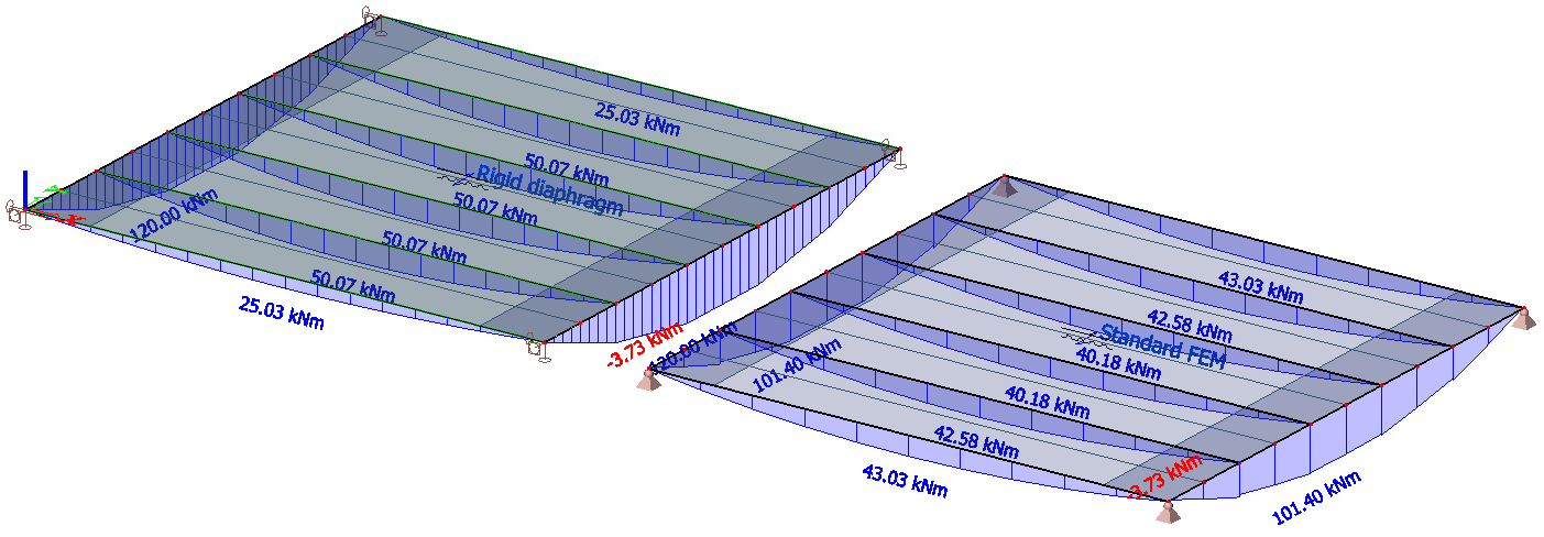
In the model on the left-hand side, the composite deck is modelled using a rigid diaphragm. The uniform load is thus transferred to the beams using a load panel logic: the load always goes to the closest beam. The bending stiffness of the composite deck is not taken into account in the analysis.
The bending moments show clearly, that the 2 edge beams receive only half of the load taken by the inner beams.
FEM plate
In the model on the right-hand side, the composite deck is modelled using a FEM plate. The bending stiffness of the deck is taken into account.
The bending stiffness of the deck has a significant impact on the distribution of the loads on the beams. All 6 beams receive roughly the same load, unlike in the previous example. Because the edge beams have the same cross-section as the inner beams, their stiffness tends to attract more load than the inner beams, leading to slightly higher value of bending moment than the inner beams.
In the girders, the maximum bending moment is approximately 15% less than in the other model. That difference is taken by the bending stiffness of the deck in its central part. Also, a small negative moment is visible at the corners, mostly caused by small numerical singularities near the supports.
The FEM plate approach, although certainly closer to the reality, leads to results that do not match traditional hand calculation.