Composite Analysis Model: Diaphragm Types
This chapter shows a comparative example of the analysis of a composite floor using various types of diaphragm.
The structure is a 2-bays composite floor supported by 6 columns. A horizontal concentrated load is applied along an edge, near the centre column, with a small eccentricity. The first model uses a rigid diaphragm, the second one a semi-rigid diaphragm and the third one a flexible diaphragm. The deformed shapes are presented in top view. In order to emphasize the specific behaviour of each type of diaphragm, the deformation scale is not the same for all 3 models.
Rigid diaphragm
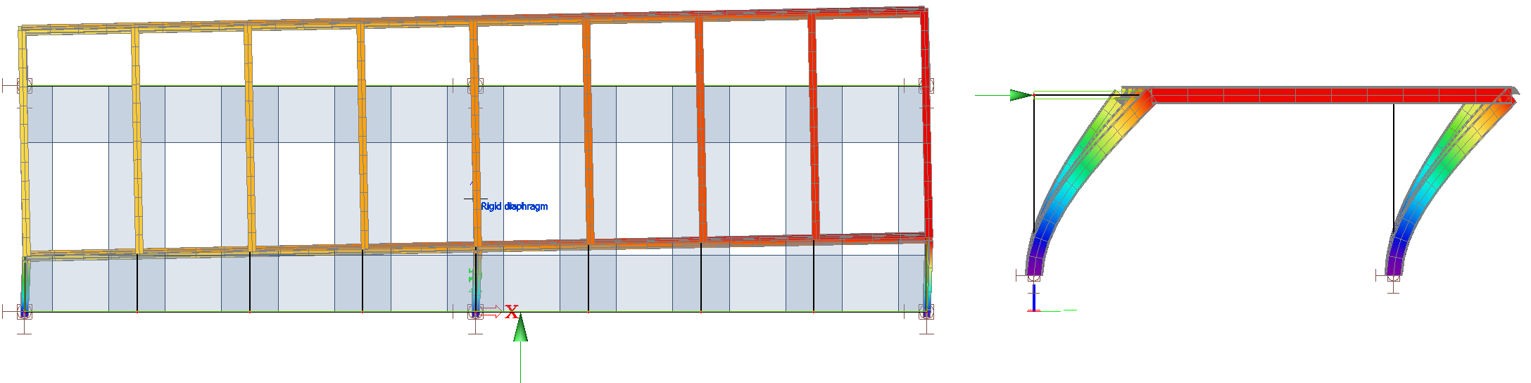
A rigid diaphragm is perfectly rigid in its own plane. It is visible here, that the diaphragm is slightly rotated as a rigid body by the eccentric load and its rectangular shape is perfectly kept. The displacement of the floor is mostly due to the deformation of the columns.
Semi-rigid diaphragm
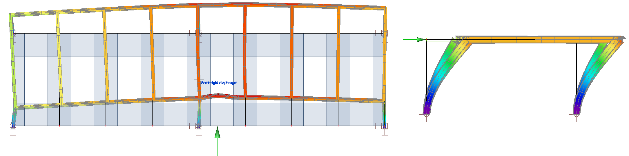
A semi-rigid diaphragm uses the real in-plane stiffness of the deck for the analysis. In this case, the displacements are due partly to the deformations of the diaphragm and of the columns. The initial rectangular shape of the deck is not kept (slight in-plane curvature) and a bump is visible in the beam where the load is applied.
Flexible diaphragm
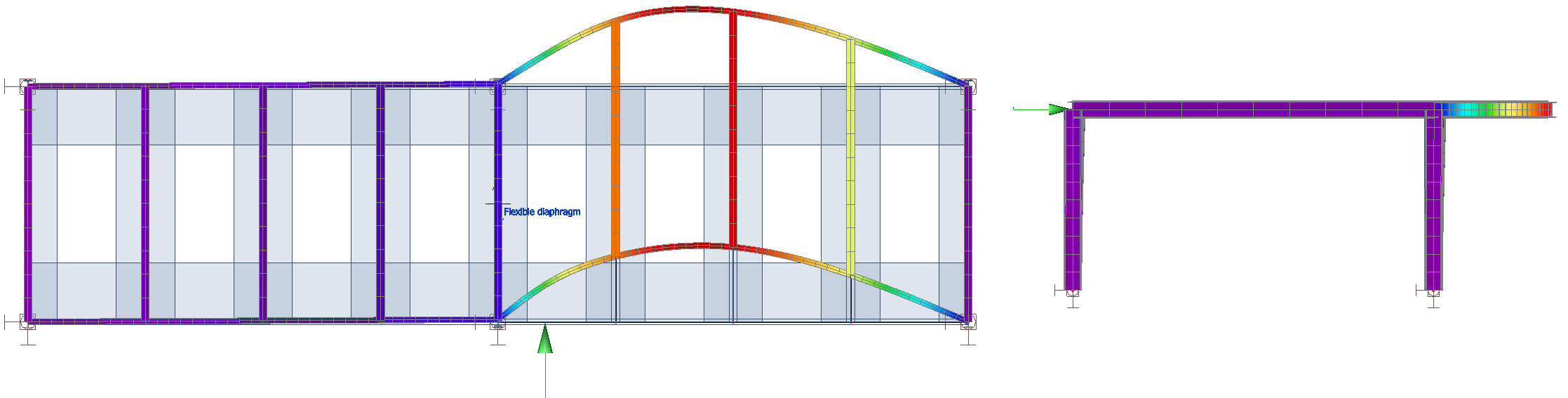
A flexible diaphragm has no in-plane shear stiffness. Therefore, it cannot act as a rigid body. It can only transfer axial forces. The displacements are mostly due to the deformation of the beams, which are much more flexible than the columns in this particular case. The floor is entirely deformed by the applied load.
Additionally, in the case of a typical metal deck, made of a profiled steel sheeting, the axial stiffness of the diaphragm can transfer loads only in the direction parallel to the corrugation of the sheeting (see picture below, left-hand side). In the direction perpendicular to the corrugation, the stiffness is extremely low and does not transfer any load across the diaphragm (see picture below, right-hand side).
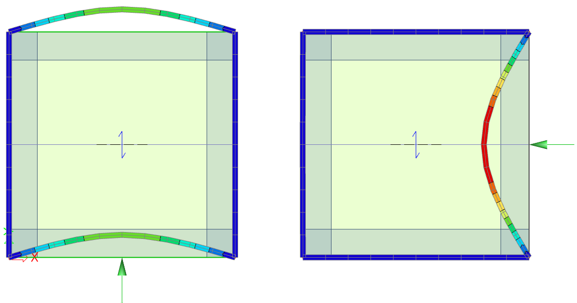
In the case of a metal deck, secondary beams usually ensure in-plane load transfer in the direction perpendicular to the corrugation of the sheeting.