Composite Checks
Composite code checks are based on the Open Checks technology and SCIA Design Forms. However, in order to avoid duplicate input of some of the data and to take most advantage of the CAM, all input needed for composite checks have been centralized in the composite service in the Composite Beam Data member attribute and in the Composite setup.
This chapter gives detailed information about the settings available in the Composite setup and in the Composite Beam Data which are related to the composite checks.
Some general information about how to use the checks is also provided. Theoretical background about the content of the checks is not provided here. References to the appropriate code articles are usually provided in the detailed output of the checks themselves.
For more information about Open Checks and SCIA Design Forms, please refer to "Open Checks: Link with SCIA Design Forms".
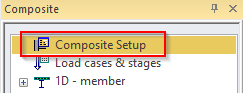
Composite Setup
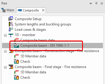
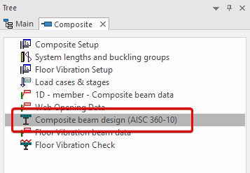
The composite setup is accessible from the composite service tree.
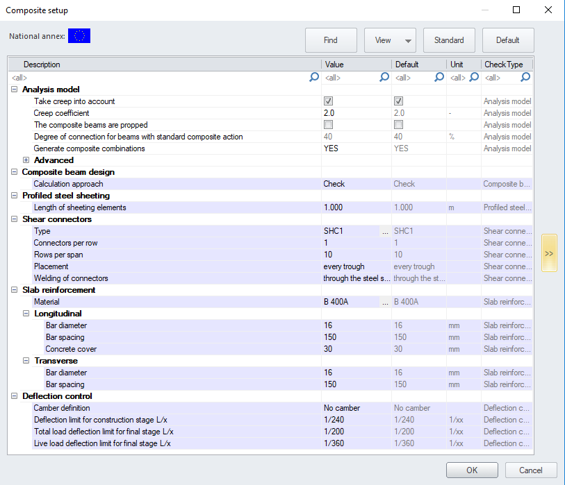
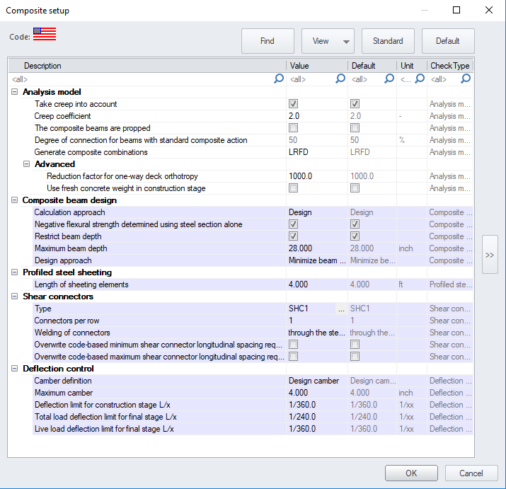
The settings related to the analysis model (CAM) have been detailed already in the previous chapter "Composite Analysis Model in SCIA Engineer". The rest of the settings are related to the composite checks. Most of them define default settings to be used for composite members without specific settings. All settings can be overridden by means of Composite Beam Data attributes (see next chapter "Composite Beam Data").
| Composite beam design | ||
| Calculation approach |

|
defines how the beam and shear connectors are handled when the composite beam design/check is carried out:
|

|
defines how the beam and shear connectors are handled when the composite beam design/check is carried out:
|
|
| Negative flexural strength determined using steel section alone |
defines whether the reinforcement bars in the deck should be taken into account or not when determining the negative flexural strength of the composite cross-section.
Note: When designing composite members, the default setting (checked) may result in a less conservative cross-section if considerable negative moment exists on the member, however, it is often the preferred approach since the alternative approach (determining the negative flexural strength from the plastic stress distribution on the composite section) will calculate the actual number of studs needed in each region of negative moment. This is often impractical since these regions are not clearly defined during the stud installation process. |
|
| Restrict beam depth |
defines, if the depth of the beam cross-section should be restricted to a given value when optimizing the beam during design. |
|
| Maximum beam depth |
the maximum depth value of the beam cross-section when optimizing the beam during design. |
|
| Design approach |
defines the design approach to be used for beam design. Depending on the selected approach, the target degree of composite action is defined as follows and used in both the analysis model and the design:
|
|
| Target degree of composite action |
defines the target degree of composite action in case of user-defined Design approach. This value is used in both the analysis model and the design. |
|
| Profiled steel sheeting | ||
| Length of sheeting elements | this value is relevant for the steel code check. It is used to calculate the stabilizing effect of a metal deck on steel beams for lateral torsional buckling. | |
| Shear connectors | ||
| Type |
type of shear connectors to be used for composite action, selected from Shear Connectors Library. |
|
|
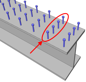
Connectors per row |
|
number of connectors per row (perpendicularly to the axis of the beam). In the case of the Design calculation approach, the program will use the value of Connectors per row as the maximum number of rows allowed in the design. The actual number of rows used in the design may be less than the value entered when possible. |
|
|
number of connectors per row (perpendicularly to the axis of the beam). In the case of the Check calculation approach, the value used for the total number of studs from zero to maximum moment is taken as number of Connectors per row multiplied by the ‘Number or rows’. In the case of the Design calculation approach, the program will use the value of Connectors per row as the maximum number of rows allowed in the design. The actual number of rows used in the design may be less than the value entered when possible. |
|
|
|
total number of rows of connectors in one span; used in case the corrugation of the sheeting is parallel to the beam Used only for Check calculation approach |
|
|
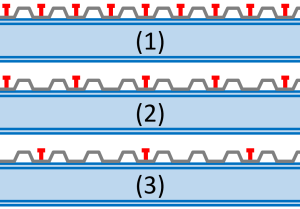
Placement |
|
spacing of the rows of connectors along the beam, defined as the number of waves between the rows of connectors. Used only for ‘check’ calculation approach, for beams perpendicular to the corrugation of the profiled steel sheeting. Possible values are: - every trough - every 2nd trough - every 3rd trough Used only for Check calculation approach |
|
Number of rows (between points of min & max moment) |
|
number of rows of connectors between the points of zero and maximum moment. Used only for Check calculation approach |
| Welding of connectors |
method of welding of the shear connectors
|
|
| Overwrite code-based min shear connector longitudinal spacing requirement |
allows for a specific value to be entered for the minimum shear connector spacing in the longitudinal direction. This value will overwrite the code-based spacing requirement and can be entered below for minimum shear connector longitudinal spacing. |
|
| Overwrite code-based max shear connector longitudinal spacing requirement |
allows for a specific value to be entered for the maximum shear connector spacing in the longitudinal direction. This value will overwrite the code-based spacing requirement and can be entered below for maximum shear connector longitudinal spacing. |
|
| Minimum shear connector longitudinal spacing. |
user defined minimum shear connector longitudinal spacing value. |
|
| Maximum shear connector longitudinal spacing |
user defined maximum shear connector longitudinal spacing value. |
|
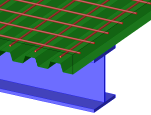
| Slab reinforcement | ||
| Material |
steel material for the reinforcement in the concrete of composite decks. |
|
| Longitudinal |
Bar diameter, bar spacing and concrete cover of reinforcement bars in the slab parallel to the beam |
|
| Transverse |
Bar diameter and bar spacing of reinforcement bars in the slab perpendicular to the beam |
|
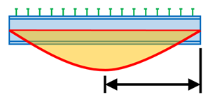
| Deflections | ||
|
Camber definition |
type of definition of the camber for composite beams, taken into account in deflection checks or design:
|
|
|
Maximum Camber |
maximum allowed value of camber, used when the required camber is calculated by the program. |
|
| Camber value |
camber value for type absolute, defined as a fixed length |
|
| Camber value L/x |
camber value for type relative, defined as a ratio of the span length, e.g. L/200 |
|
| Deflection limit for construction stage |
limit allowable deflection for deflection check in construction stage, defined as a ratio of the span length |
|
| Total load deflection limit for final stage |
limit allowable deflection for total deflection check in final stage, defined as a ratio of the span length |
|
| Live load deflection limit for final stage |
limit allowable deflection for live deflection check in final stage, defined as a ratio of the span length |
|
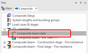
Composite Beam Data
The composite beam data is accessible from the composite service tree. It can be added to any composite beam and overrides the inputs from the Composite Setup.
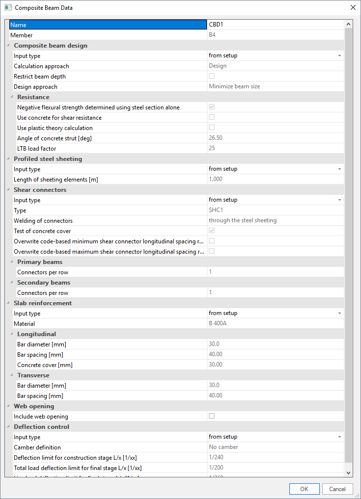
The composite beam data attribute allows to override for a specific composite beam the default settings defined in the composite setup. For each group of settings (e.g. shear connectors or slab reinforcement) it is possible to separately specify if the default settings must be used or rather some customized values.
Shear connectors library
The composite shear connectors library is accessible as any standard library, from the Libraries menu (composite sub-menu), from the main tree view (Libraries>Composite branch) and from the composite beam data attribute, when assigning shear connectors to a composite beam (see above "Composite Beam Data"). A selection of pre-defined shear connectors is available in the system library ( ).
).
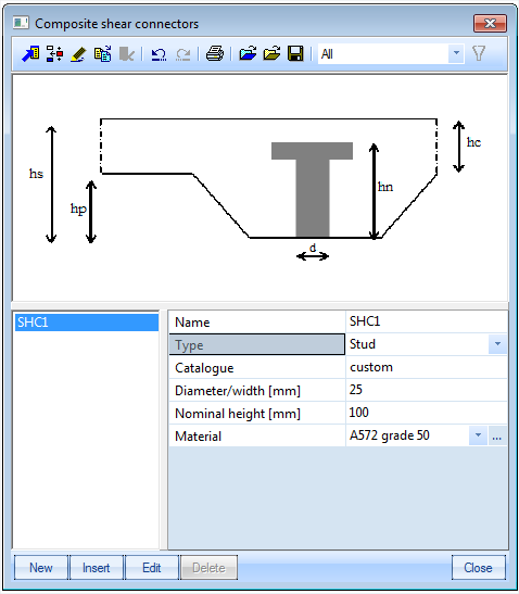
| Name |
name of the shear connector type |
| Type |
generic type of connector; possible values are Stud, Hilti, Channel and Bar hoop |
| Catalogue | catalogue designation, can be any text, keyword... may be used for filtering the library (using the catalogue filter). Typical use would be the name of the manufacturer or the name of the product range |
| Diameter/width | cross-sectional dimension of the connector; typically, diameter of a stud |
| Nominal height | nominal height of the connector for the calculation of the resistance |
| Material | steel material of the connector |
All settings above are transmitted to the composite checks. They do not affect the analysis model.
Composite Checks
All composite checks are accessible from the composite service tree. They are displayed after a successful analysis of the structure (analysis results available).
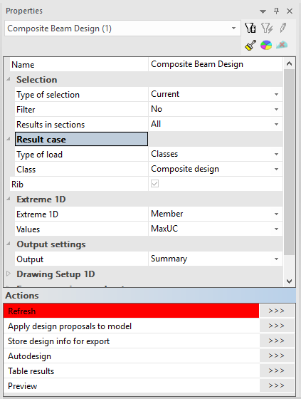
General use of the composite checks
All composite checks use the same standard settings as other result services in SCIA Engineer. Results are available as text and graphical output. The text output can be obtained in a summary table output (only main results, one row per result) or as detailed output (full details of check, with intermediate results…).
| Name | name of the selected check |
| Selection | selection of entities on which the check will be performed (all, current, advanced, named selection, design group) |
| Type of loads | type of actions to be used for the check (load case, combination, result class) |
| Load case | selected load case for the check (in case type of loads = load case) |
| Combination | selected load case combination for the check (in case type of loads = combination) |
| Class | selected result class for the check (in case type of loads = class) |
| Combinator strategy |
strategy used for handling envelopes
|
| Filter | standard filter on members (wildcard, cross-section, material, layer) |
| Print combination key | when enabled, print the combination key along with the results in the text output |
| Values | selection of the value(s) for graphical representation |
| Extreme | extreme selection mode (section, local, member, interval, cross-section, global) |
| Output |
text output format
|
| Drawing setup 1D | detailed configuration of graphical output |
| Section | sections for which the check must be performed on each selected member (all, ends, inputted, inputted+ends) |
| Refresh >>> | action button: perform the check |
| Autodesign >>> | action button: autodesign according to selected settings; filter must be cross-section (see more detailed explanation in Autodesign manual "AutoDesign - Global optimization") |
| Split CSS >>> | action button: split cross-section optimization according to unity check value of selected members |
| Unify CSS >>> | action button: assign the same cross-section to several members having different cross-sections |
| Preview >>> | action button: display the text output window |