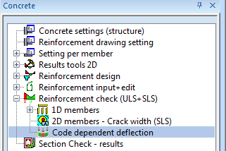
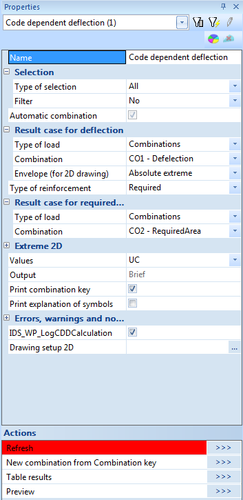
Command for Code dependent deflection
Calculation Code dependent deflection can be run directly in Concrete tree via command Code dependent deflections (Concrete > Reinforcement check ULS+SLS). This command is visible, if linear calculation is done and Post processing environment is set to Default in Project data, see "Setting Project data"
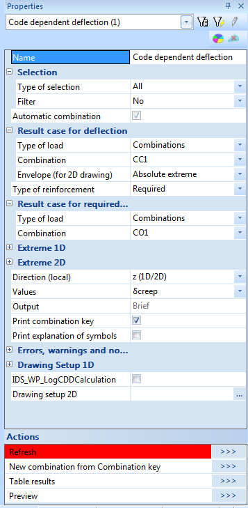
There is possible to evaluate deflection for 1D and 2D in one command and properties in these command are filtered according to, if in the project are only 1D members, only 2D members or both
Group selection
There is possible to select ,which 1D and 2D members will be taken into account for Code dependent deflection and for evaluation of the results. If some selection of members is done, only for this selection non-linear stiffness (reduced stiffness by taking into account cracking and creep), for others members linear stiffness will be used. It follows, that for different selections, different results can be obtained, therefore:
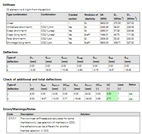
- there is new group CDD selection in the header of numerical outputs, where is the list of the members ,which will be used for code dependent deflection is presented
- there is note N7/1, if not all members from the structure , are used for code dependent deflection

the code dependent deflection is recalculated, if new selection is done and some selected members are not in CDD selection
List of members from Selection and CDD selection can be different, because for evaluation numerical or graphical output only some member from CDD selection can be selected
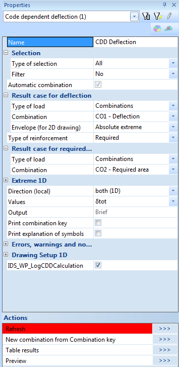
Automatic/manual input of combination
The EN code prescribes a different load input to analyse total and additional deflection limits.There are two options for inputting/generation combination, see "Combination for CDD":
- Automatic combination ( check box Automatic combination is ON) - only the combination given for calculating the total deflection has been required as the user's input Result case for deflection. The rest of the necessary sub-combinations to evaluate creep and the immediate part of the deflection are automatically generated by the program
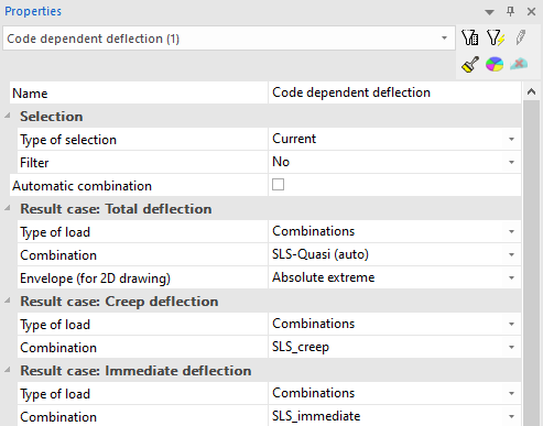
- Manual input of combination ( check box Automatic combination is OFF) - the user can define own combination for calculation total deflection (Result case: Total deflection), creep (Result case: Creep deflection) and immediate deflection (Result case:Immediate deflection). The combination for immediate and creep deflection has to be linear combination, it means that creep and immediate deflection will be the same for all sub-combinations generated from combination for total deflection.
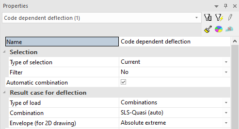
Group Result case for deflection/ Result case: Total deflection
Load case/combination or class can be defined in the group, which will be used for calculation code dependent deflection. For automatic generation of combinations from defined results case a special combination for calculation immediate deflection and deflection caused by creep, will be created on the background. There are supported following result cases:
- load cases
- SLS combination (Linear-serviceability, Envelope-Serviceability, EN-SLS Characteristic, EN SLS Frequent, EN SLS Quasi permanent, )
- Classes, which contain load cases or only SLS combinations
In case of manual input combination (Automatic calculation is OFF) the name of group Result case for deflection is changed to Result case: Total deflection
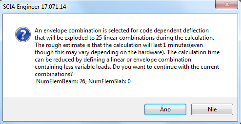
Envelope combination is exploded to linear combination on the background.Deflection and FEM analysis is calculated for each linear combination and extreme deflection form all linear combination is evaluated. If number of linear combinations after exploitation from envelope combination is bigger than 10, program gives some warning with time estimation
Group Result case: Creep deflection
The group is visible only in case that Automatic deflection is OFF. There is possible to define load case/combination which will be used for calculation creep deflection. There are supported following result cases:
- load cases
- only SLS combination (linear - serviceability)
Group Result case: Immediate deflection
The group is visible only in case that Automatic deflection is OFF. There is possible to define load case/combination which will be used for calculation immediate deflection. There are supported following result cases:
- load cases
- only SLS combination (linear - serviceability)
Type of reinforcement
Three type of reinforcement are supported for code dependent deflections:
- required reinforcement -it is reinforcement designed by the program in command Reinforcement design. It is a sum of statically required reinforcement (reinforcement designed for normal forces and bending moments, longitudinal reinforcement designed for tensile force caused by shear and torsion) and reinforcement designed according detailing provisions.
- provided reinforcement - it is reinforcement, which is input in Design defaults or Concrete member data via library Provided reinforcement
- user reinforcement - it is reinforcement input by the user
Load case/combination/class, which will be used for design required and provided reinforcement, can be defined in group Result case for required reinforcement
type of reinforcement which is used for code dependent deflection is presented in numerical output too. If required/provided reinforcement was not calculated or user reinforcement was not inputted in some sections of 1D members or elements of 2D member, than linear stiffness for uncracked section/element or 10% of linear stiffness for cracked section/element is used and program gives some warning
If the required or provided reinforcement for 1D members is already designed for selected combination in Result case for required reinforcement and selected selection, the designed required/provided reinforcement will be used, otherwise required/provided reinforcement will be designed before calculation of code dependent deflection for selected combination and selection
The required/provided reinforcement of 2D member, which is calculated for Location = In centres and for System = LCS mesh elements is supported for code dependent deflection of 2D members. If the required or provided reinforcement for 2D members is already designed for selected combination in Result case for required reinforcement, selected selection, Location = In centres and for System = LCS mesh elements , the required/provided reinforcement will be used, otherwise required/provided reinforcement will be designed before calculation of code dependent deflection for selected combination and selection.
Group Result case for required reinforcement
Load case/combination or class can be define in the group, which will be used for design required or provided reinforcement, in the case that for selected selection and combination, required or provided reinforcement is not already calculated..This group is visible for Type of reinforcement = Required or Type of reinforcement = Provided. There are supported following result cases:
- load cases
- ULS combination (Linear-ultimate, Envelope-Ultimate, EN-ULS..., )
- Classes, which contain load cases or only ULS combinations
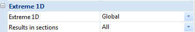
Group Extreme 1D
This group is visible only for project with some 1D members and user can select for which extreme (Extreme 1D) the results for 1D will be presented and in which sections (Results in sections)
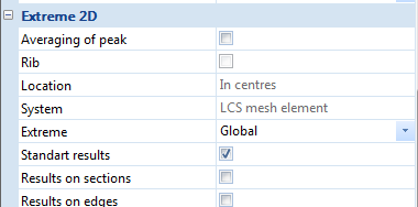
Group Extreme 2D
This group is visible only for project with some 2D members and user can select for which extreme (Extreme 2D) the results for 2D will be presented and how will be presented(Standard results, Results on , Results on edges) . Except the fine following parameters can be define:
- Averaging of peaks - internal forces and required/provided reinforcement is reduced, if some Averaging strip is defined
- Rib - check box if effective width of the slab will be taken into account or not. If the check box is OFF, then deflection of the rib is calculated as deflection of standard 1D member (1D member on eccentricity) which is linked to 2D member. It follows:
- required reinforcement is designed on 1D and 2D member without taking into account effective width of the rib.
- 1D deflection is calculated only for cross-section which is defined in rib properties and for internal forces without taking into account check box RIB
If the check box is ON, then deflection of the rib is calculated with taking into account effective width defined in RIB properties. It follows
- required reinforcement is designed on 1D and 2D member with taking into account effective width of the rib
- 1D deflection is calculated for new cross-section created from rib cross-section (cross-section defined in properties of the rib ) + part of the slab with effective width and for internal forces for 1D member and 2D meshes inside effective width , which are recalculated to centre of gravity of new cross-section
- Location - the stiffness and required/provided reinforcement is calculated in centre of 2D elements
- System -internal forces and required/provided reinforcement is related to LCS of mesh elements
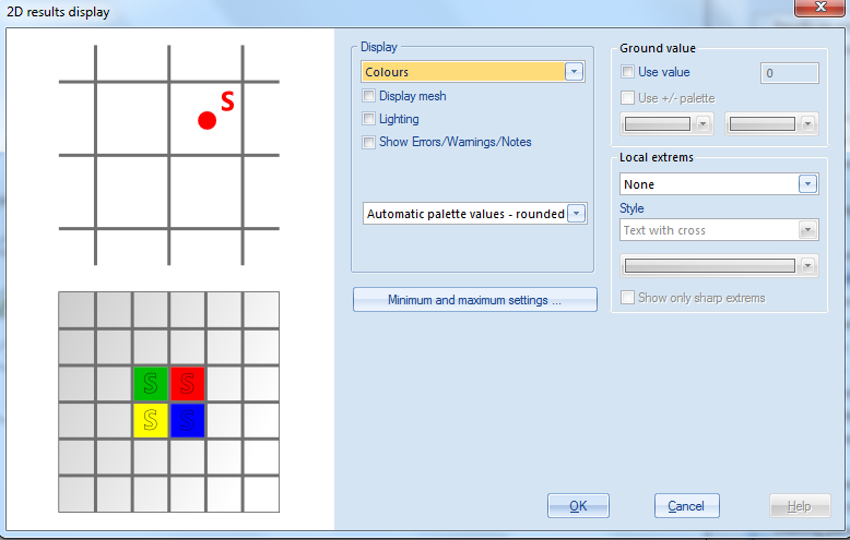
Direction(local)
There is presented deflection in two directions for 1D member (deflection in y and z direction), but only one deflection for 2D member (z direction). User has three possibilities for presentation deflection of 1D member in graphical output :
- z(1D/2D) - deflection in z axis of LCS of 1D member and 2D member is presented
- y(1D) - only deflection in y axis of LCS of 1D member and deflection in z axis of LCS of 2D member is presented
- both (1D) - deflection in both directions of LCS of 1D member and deflection in z axis of LCS of 2D member is presented
Values
There are presented the following output values in graphical and numerical output:
- UC - unity check of check deflection in both direction (y and z) of 1D member and in direction z for 2D member
- dtot - total (long-term)deflection with taking into account cracking and creep
-
dtot,lim - maximal (limit) total deflection
-
dadd - additional deflection
- dadd,lim - maximal (limit) additional deflection
- dlin - linear (elastic) deflection
- dimm -immediate deflection
- dshort -short-term deflection with taking into account only cracking
- dcreep -deflection caused by creep
-
dshr -deflection caused by shrinkage
presentation values of deflection for 1D member (deflection in y or z axis of LCS) in graphical window depends on setting in property Direction (local)
only deflection in z direction of LCS of 2D member is presented for 2D member
Output
Making the code-dependent deflection analysis more transparent for the users, the three type of output are available in current version:
- brief
- standard
- detailed
Standard and detailed output can be presented too via Table results for specific extreme presented as a row in the table (by double click on it)
Brief output
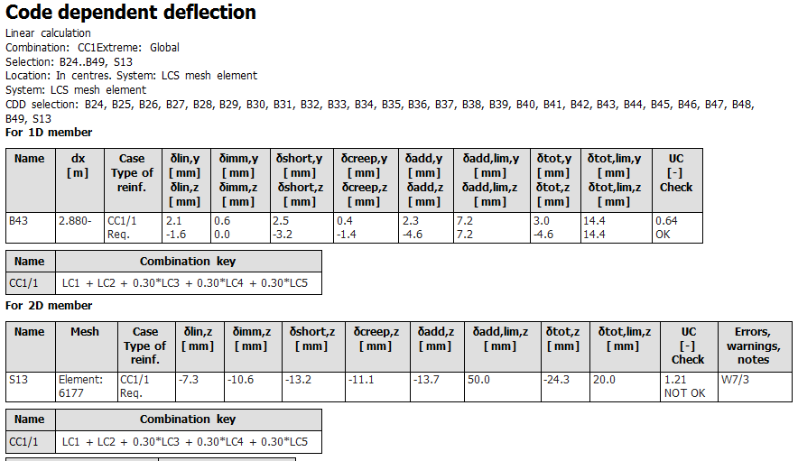
There is presented only two tables of deflection with the the basic values of deflection
- deflection for 1D member
- deflection for 2D member
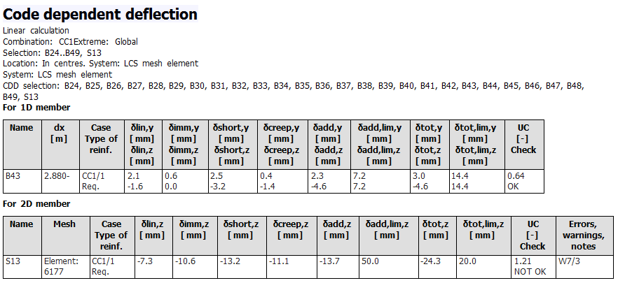
There are presented following values in numerical output
| dlin,y(z) | Linear (elastic) deflection in direction of y(z) axis LCS of the member calculated for linear stiffness and defined combination for deflection |
| dimm,y(z) | Immediate deflection in direction of y(z) axis LCS of the member after applying permanent and longterm variable load calculated for short-term stiffness and immediate combination |
| dshort,y(z) | Short-term deflection in direction of y(z) axis LCS of the member with taking into account only cracking calculated for short-term stiffnes and total combination (defined combination in the the Result case for deflection) |
| dcreep,y(z) | Deflection caused by creep in direction of y(z) axis LCS of the member calculated as difference between deflection calculated for long-term and shorter stiffness for combination for calculation creep deflection |
| dadd,y(z) |
Additional (harmful) deflection in direction of y(z) axis LCS of the member, which is created after applying variable load with taking into account deflection caused by creep calculated. The value is calculated as difference between total and immediate deflection dadd,y(z) = dtot,y(z) - dimm,y(z) |
| dtot,y(z) |
Total (long-term) deflection in direction of y(z) axis LCS of the member with taking into account creep and cracking calculated as sum of short-term and deflection caused by creep dtot,y(z) = dshort,y(z) + dcreep,y(z) |
| dadd,lim,y(z) | Maximal additional (harmful) deflection in direction of y(z) axis LCS of the member |
| dtot,lim,y(z) | Maximal total (long-term) deflection in direction of y(z) axis LCS of the member |
| UC | Unity check of additional and total deflection in both directions |
| Type of reinf. |
Type of reinforcement, which is used for calculation of stiffnesses None – no reinforcement , linear stiffness is used Reg. – required reinforcement Prov. – provided reinforcement User – user (REDES, 2D meshes or free bars) |
| Check | Status of the check |
| E/W/N | Errors/Warnings/Notes, see SR 1340 |
Standard output
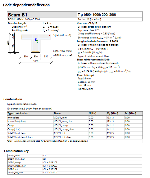
Standard output contains the following information about calculation:
- header with the picture of the cross-section and basic input data
-
table of combinations used in the calculation (name, combi-key, internal forces)
- table of stiffnesses (value of stigffnesses for each type of deflection)
- table of deflection
- table of check
Detailed output
Detailed output contains the following information about calculation:
- header with the picture of the cross-section and basic input data
- table with input data and reinforcement
-
table of combinations used in the calculation (name, combi-key, internal forces)
- detailed calculation stiffnesses for each type of deflection(cross-section characteristic, reinforcement, calculation average stiffness...)
- table of stiffness
- table of deflection
- table of check

Print combination key
Table with combination key (list of load cases with load coefficient ) of Result case for deflection for each table separately(for 1D and 2D member) is presented in numerical output, if the check box Print combination key is switched on. The list of load cases is presented for each dangerous combination (index of combination), which is presented in column Case in table of numerical output.
Print explanation of symbol
Table with explanation of symbol for each table separately(for 1D and 2D member) is presented in numerical output, if the check box Print explanation of symbol is switched on.
Group Errors,warnings and notes settings
There is possible to present errors , warnings and notes, which occurred during calculation, in numerical and graphical output. User can select in this group:
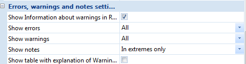
- if the errors, warning and notes will be presented in the header of the numerical output (check box Show information about warnings in Result header)
- if the explanation of errors, warning and notes will be presented in the numerical output (check box Show table with explanation...)
- how the errors, warnings and notes will be presented in numerical and graphical output (properties Show errors, Show warnings and Show notes)
only numerical output of errors, warning and notes is supported for 2D member in version 17.0
The following errors, warnings and notes can occur during calculation of deflection
| Index | Type | Description | Solution |
| W7/1 | Warning | The limit total deflection in (y) direction of LCS member is exceeded | To increase dimension of cross-section or to increase area of reinforcement (manually or by using Coefficinet for increasing amount of reinforcement defined in Concrete setting or concrete member data) |
| W7/2 | Warning | The limit additional deflection in (y) direction of LCS member is exceeded. | |
| W7/3 | Warning | The limit total deflection in (z) direction of LCS member is exceeded | |
| W7/4 | Warning | The limit additional deflection in (y) direction of LCS member is exceeded. | |
| W7/5 | Warning | The linear stiffness was used for the calculation, because section is uncracked and there is no reinforcement | To change type of reinforcement, which is used for calculation, or to design required or provided reinforcement or to input user reinforcement |
| W7/6 | Warning | Only 10% of the linear stiffness was used for the calculation because the section is cracked and no equilibrium had been found | To increase dimension of cross-section or to increase area of reinforcement (manually or by using Coefficinet for increasing amount of reinforcement defined in Concrete setting or concrete member data) |
| N7/1 | Note | Nonlinear stiffnesses are calculated only for some members (CDD selection),so for different CDD selection, the deflections can be changed | To use all 1D and 2D members for CDD calculation |
| E09 | Error | Rib is not supported, the linear stiffness was used for the calculation |
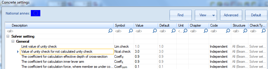
The value of unity check is loaded from Concrete setting (value Ncal.check), if errors is occurred during the calculation
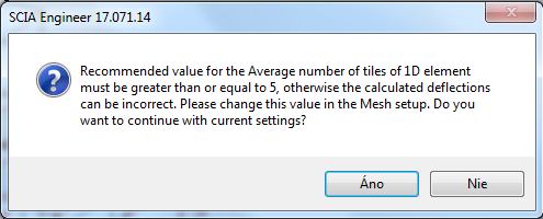
Except errors/warning and notes above, two special warning can be appeared before running of calculation:
- warning about number of combinations, which is used for CDD calculation
- warning about number of 1D elements
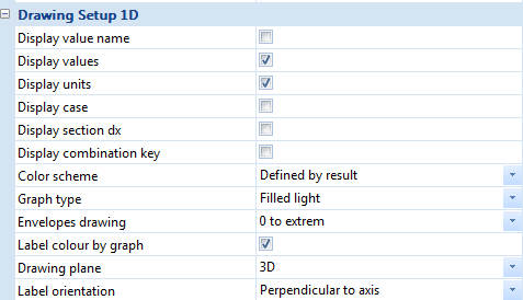
Group Drawing setup 1D
The user can set how will be presented result for 1D members in graphical window in this group
Group Drawing setup 2D
The user can set how will be presented result for 2D members in graphical window in this group