Theoretical background
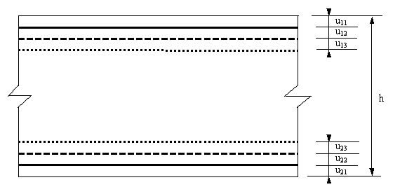
Reinforced concrete 2D structures handled by SCIA Engineer (Walls, Plates and Shells) are usually reinforced by two systems of steel reinforcement nets consisting of 2 or 3 reinforcement courses situated more or less close to both surfaces of the 2D member.SCIA Engineer puts no principal restrictions upon the absolute position of reinforcement courses within the cross-section, its axial concrete cover describes the position of each reinforcement course. However, there are relative restrictions: all concrete covers must fulfil some rules to prevent ambiguousness of the geometric definition of the design task. These rules are described in the part of the SCIA Engineer manual. Yet it must not be forgotten that there might be other, more complex situations in the cross-section than symbolised by the figure 1:
- The crossing reinforcement bars of individual layers do not need to touch each other; they might be placed at larger distances from each other within the cross sections.
- The surfaces of bars are usually corrugated so that there is, as a rule, a greater distance between two crossing bars than expressed by their characteristic bar diameters.
- Last but not least, in very thick plates, e.g. foundation slabs, two layers or bars bundles in one layer are used, so that the representative axial distance (of the point of gravity) and the representative bar diameter itself are two independent quantities and qualities, which must be defined independently on input in order to carry out reliable analysis.
In Walls, being (theoretically) subjected to forces acting in their planes, the (by definition symmetric) positions of reinforcement nets are of no static interest; however, the cross-section geometry (concrete covers and bar diameters) is of interest for the Crack Proof algorithm (if implemented). Thus, the Wall design branch comprises the same cross-section input dialog as the Plate and Shell models.
In Plates and Shells, on the contrary, the reinforcement covers influence the effective static height of the reinforcement courses in the cross-section subjected (also) to bending, thus having fundamental meaning for the design process. The covers are related to the faces. Thus, it is necessary to distinguish them clearly from each other. Because Plates are (still) the structural type most frequently used in the practice, SCIA Engineer use originally common terms distinguishing the two faces: upper and lower face. These concepts have to be given mathematically exact meaning, which makes them acceptable for Shells, too: the lower face is the structural plane edge in direction of the positive planar axis Zp; the upper face is opposite to it. Finally, the symbol -Zp appears generally in the output protocol instead of the term upper face; the symbol +Zp symbolises lower face. In Walls, there is no need of distinguishing both structural edges; nevertheless, out of formal reasons (simplification), if the concept of upper face appears in connection with Walls it means both faces.
The reinforcement courses are, correspondingly to their relative position in the cross-section, called the outer(most), middle (if any) and inner(most) ones. This verbal distinguishing is in the mathematical formulation replaced by assigning them the ordinal numbers 1, 2 and 3 (if three reinforcement courses are specified). The same double identification may be given to other associated terms like reinforcement angles, design forces, effective static heights, internal forces levers, etc. So we can say, e.g., about reinforcement angle α, β, γ meaning the same, when alternately indicating α1, α2, α3. There is no indication that this ambiguity of terms should cause confusion; as a fact, there is no ambiguousness for the correspondence of both systems of denotation is clearly defined.
Note that each reinforcement course can hold up to 10 reinforcement layers.
The terms of the reinforcement concrete theory are used in accordance with the general structural use or they strictly follow the rules postulated by the standards implemented in SCIA Engineer. However, for SCIA Engineer deals with several national codes, it is probable that this or that term or formulation would appear somewhat unfamiliar to some readers focused on the use of one code branch only. It is hardly possible to create a manual text on such special topic for international use being in all respects verbally fully conform to every country’s verbal usage. In doubts, the terminology of Eurocode will be given preference.
The design task and the output of results are performed in basic and derived units of the SI system.
Wall Design
Once a positive design force is assigned to its associated reinforcement course, the corresponding statically required reinforcement amount ai is calculated from the elementary relation:
ai = ni /σsd (i = 1,2 (,3)) [m2/m] (6)
(6) has symbolic meaning only, as we do not want to write down at this stage all the exact calculation rules for codes implemented in NEDIM (the original development name of the 2D design module system, used internally by SCIA developers, testers and supporters for quick communication). The symbol σsd stands for the effective design steel strength. Both ni and σsd may be, according to the actual code, charged with security coefficients. We are not going to discuss the problem of 1D reinforcement design; the NEDIM algorithm strictly follows special rules stipulated by national codes and associated Standards, as far as they are applicable to the 2D design.
The virtual stiffening strut of the heterogeneous concrete-steel continuum represents quite a substantial issue of the design process. While it is possible (unless the upper reinforcement percentage limit has been exceeded) to improve the bearing capacity of the cross-section on the side of the reinforcement by augmenting its amount, the bearing limit of the concrete strut is given by the height of the cross-section and the quality of concrete only; thus its limits are predestined by the input data. The concrete strut bearing capacity condition is described by the following relation:
–n3 < Ac σcd(9)
In (9) σcd represents the effective concrete design pressure strength and Ac – the concrete area of reference. In NEDIM it is generally assessed on the base of 80% of the standard design concrete pressure strength. This reduction follows the recommendation of Schleich and Schäfer in literature [2] : the compression strength of concrete is unfavourably affected by transversal tension stresses which produce cracks, parallel to the direction of pressure; this is typically the stress situation of the stiffening strut. For cracks parallel to the direction of strut, the reduction coefficient kc = 0.80 is stipulated, which is identical with the NEDIM default, whereas for cracks crossing the strut direction the value kc = 0.60 is specified! The cross-section area Ac in (9) is for Walls taken as the full unity rectangular cross-section h × 1.
Once a design pressure force ni, assigned to a reinforcement direction i, is known the compression reinforcement is calculated acc. to the following general formula:
ai = (–ni –Ac σcd) / σscd (i = 1,2 (,3)) [cm2/m](10)
In (10) σscd represents the effective design compression strength of reinforcement steel differently to (6), where σsd denotes the design tension strength; Ac is the gross sectional area. NEDIM checks if the steel reaches the compression yield strain; if not, σscd reflects the actual strain level. Some codes (ÖNORM B 4200, CSN/STN 73 1201, GBJ 10-89) stipulate different values of steel strength in tension and compression. NEDIM follows this idea by enabling different definitions of tension and compression steel strength to all code branches.
Plate Design
In the Wall model dealt with in the preceding paragraph, the internal design forces produce constant stresses all over the cross-section; thus, there is no necessity to examine the stress distribution within the cross-section. In contrast to the Wall model, for bending in Plates it is a fundamental characteristic that the stresses are non-linearly and discontinuously distributed over the cross-section. Since all of the national codes implemented in NEDIM exclude the tensile bearing capacity of concrete (ULS), the only bearing material in the tension zone (“below” the neutral axis) is the reinforcement steel. The resistance of concrete is exploited in the compression bending zone only.
Figure 3 shows symbolically one possible equilibrium situation in the reinforcement courses 1 and 2 (Fig. 3a,b) as well as in the concrete stiffening strut, i.e. in virtual course 3 (Fig. 3c). In Fig. 3, the face subscript is generally omitted, for the discussion is equally valid for both faces. The distribution of the concrete compressive stress in Fig. 3 is not related to a specific code. However, the codes implemented introduce different basic notions of the concrete compressive stress distribution. The assumption of the compressive stress distribution is in affinity to the σ-ε diagram of the concrete material.
EUROCODE 2 allows for all national code assumptions. Actually, NEDIM keeps to the parabola-constant concrete compressive stress distribution assumption. EC 2 introduces a new approach for the shear proof, which explicitly operates with the notion of the virtual (shear) strut. It also formulates a new approach to the consideration of the interaction (m/n) ⇔ v. In compliance with this notion, the shear force may cause an increase of the required net reinforcement. This phenomenon was investigated by the Author of NEDIM and in 1999 it was implemented into the EC 2 design branch as well as into all other design branches following the same (or similar) approach. For more detail on this phenomenon, named Shear Effect by the Author of NEDIM, see paragraph Advanced notes on "Shear Effect".
EN 1992-1-1:2004 is the EC 2 amendment of the preliminary European Norm ENV 1992-1-1:1991. Extensive modifications to the original text have been made in all sections. Especially the paragraphs on shear proof, crack control and minimum reinforcement control have been expanded and diversified, e.g. (a) all "reasonable" assumptions of concrete stress-strain diagram are allowed, namely the three basic cases: pressure block, linear-constant and parabola-constant. For the block distribution, restrictions to height and stress have been introduced: λx and η fcd ; (b) the recommended value of the strength reduction coefficient in fcd = αcc fctk,0.005 / γc is αcc = 1.0 (for the EC2 code family is typically αc = 0.85); (c) the strength reduction coefficient ν1 in the formula for the shear strut resistance vRd,max is more diversified and the coefficient αcw of the same formula expresses the effect of normal stress upon vRd,max on three intensity levels; (d) the crack calculation formula (direct control) resembles that of DIN 1045-1, however, the crack distance formula depends here on 4 parameters.
In Plate models the statically required tension reinforcement of a design course is calculated by the basic formula :
ai =mi /(zi σs,eff) (i = 1,2 (,3)) [cm2/m] (11)
In (11) the special moment symbol mi for the design moment associated with the reinforcement course is substituted for the common symbol ni for design force in order to avoid confusion. The stress symbol σs,eff has a quality comparable with that introduced by (6) for Walls; it again represents the effective design steel strength for all codes.
The internal forces lever zi in (11) makes out the formal difference of (6) and (11); factually, there is no difference between them, since the quotient mi /zi equals the steel design force Zi, which constitutes with the opposing concrete pressure zone resultant force Di the force couple representing the design bending moment mi; thus, we formally obtain (6) by substituting ni = Zi =mi /zi into (11).
(11) reveals the fundamental meaning of the internal forces lever z for the design algorithm. As a fact, by introducing the transformation formulae (3) for Shells it was made clear enough that the knowledge of the proper value of inner forces lever is indispensable for correct reinforcement design.
In NEDIM the internal forces lever z is calculated by the following procedures:
- For DIN 1045 and ÖNORM B 4200 interpolation formulae for the value of z were developed. The maximum approximation error amounts up to 2%, however.
- For all other codes (following the first two on the time scale) analytic integration procedures for the basic assumptions of stress block, linear-constant and parabola constant stress function were devised; they yield exact pressure integrals.
The stiffening function of the concrete medium is not as transparent in Plates as in Walls. In Plates we have to do with force couples representing inner bending moments. The concrete pressure stresses are not constantly distributed over the cross-section. Thus, a direct application of the concrete strut bearing capacity limit condition (9) is not possible in Plates. NEDIM had used some approximate approaches until the best and perhaps most simply formulation of the strut bearing capacity limit was found. Instead of describing the strut control by mathematical terms, a verbal explanation of the matter relating to Fig. 3c and Fig. 3d is preferred :
- In Plates the strut design force n3 means the force couple of m3. From Fig. 3c it is obvious that m3 causes basically the same kind of stresses in its direction as the other two reinforcement design moments m1 and m2, however, with exchanged faces (i.e. m3 is of opposite sign). In this case we are not interested in analysing the situation on the opposite face; the state of stress in the stiffening strut bending pressure zone is of interest. What is the limit condition of the strut bearing capacity? What calculation value of stress integral force D3 is to be taken into account?
- The answer to this fundamental question is given by Fig. 3d : NEDIM allows for the maximum height of the bending pressure zone xmax in compliance with the design algorithm applied. If at this state of stress the equilibrium in the cross-section is not yet attained, i.e. would strengthening of the pressure zone by (pressure) reinforcement be formally required, then this is considered by NEDIM as an unambiguous indication of the bearing capacity of the stiffening strut being exceeded. The cross-section is non-designable due to concrete failure.
Till the middle of 2007 it had not been known to the Author of NEDIM that any competing software would deal with this problem at all. Neither codes nor theoretical publications on reinforced concrete design care about the state of concrete in a heterogeneous concrete-steel 2D medium. Some codes give “standardized” recommendations as to the geometrical arrangement of reinforcement in reference to the directions of the principal moments. They are concerned with stress situations which are typical for corners of floor slabs etc.
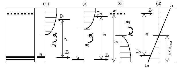
Figure 3 Equilibrium of design internal forces in a Plate cross-section : (a) reinforcement course 1; (b) reinforcement course 2; (c) concrete stiffening strut – course 3; (d) strain situation in the stiffening strut (bearing ability proof).
Shell Design
In the design of Shells, the ideas and procedures of both the design of Walls and the design of Plates are combined. The code requirements and restrictions, which seldom are formulated individually for Shells, must both be considered both for Walls and Plates. Thus, the Shell design is the most complex design model dealt with by NEDIM.
From the mechanical point of view, the stress-strain situation in cross-sections of Shells may develop from a typical "Wall pattern" with constant stress distribution to a "Plate pattern" with characteristic non-linear concrete pressure stress distribution over the bending pressure zone along with a cracked region "below" the neutral axis where there the reinforcement resists the stresses from inner forces. The special situation depends, however, on the character of external load as well as on the boundary conditions of the analysis model.
NEDIM has to manage all possible stress situations arising between the Wall type and the Plate type state of stress using one unique design model to be able to produce results consistent also with quantitatively slowly yet qualitatively abruptly changing states of stress. It would be unacceptable to have a Shell design model which, on one side, yields results fully identical with a Plate solution when there is pure bending acting, i.e. the membrane forces being zero, yet produces, on the other side, obviously distorted results whenever the membrane forces differ slightly from zero. Little change in loading must imply little change in the reinforcement design results.
As a fact, all codes were drafted focusing to the problems of 1D structural members, i.e. beams and columns. In NEDIM, many requirements and restrictions had to be given a reasonable engineering interpretation or extrapolation to fit to the special character of the 2D structures. The reinforcement at both faces consists of two mutually independent meshes with 2 or 3 reinforcement courses in generally different directions. Thus, in Shells it is not possible to proceed by simply using the solutions of the reinforcement concrete design of beams.
NEDIM creates two sets of transformed design forces assigned to individual reinforcement courses and/or the stiffening concrete strut at both faces of the analysis model. The procedure goes acc. to the formulae (4). In the assessment of the inner forces lever z the Shell design procedure resembles the Plate design. By creating equivalent inner forces {nx, ny, nxy}±Zp and their transforms {n1d, n2d, n3d} NEDIM follows a typical Wall design approach. Formally, we get two systems of design situations at both Shell faces which must be managed in two algorithmic steps in every cross-section by considering the situation on the other face. In this sense, the Shell design is organized like the Plate design.
Fig. 4c symbolizes the Shell design : there is a design force nd (subscript i = 1,2,3 is omitted) assigned to a reinforcement course at the upper face (the same procedure applies to the lower face). The symbol nd,opp is used for the virtual design force at the opposite face acting in the same direction as at the actual face; it is unimportant if there is a congruent reinforcement course parallel to that at the actual face or not. The normal force in this cross-section is in Fig. 4c denoted as nvirt (virtual normal force). The virtual bending moment mvirt is defined complementary to nvirt. Thus, the virtual normal force eccentricity (241), (242) can be estimated.
Fig. 4c demonstrates also the fact that the design at a Shell face is typically Wall design; however, the design force nd is not applied to the total cross-section area as in Walls (Fig. 4a), yet to some portion of it : Ac,eff = heff × 1.0. NEDIM assigns Ac,eff basically in accordance with the suggestions of Baumann.
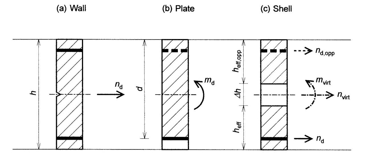
Fig. 4 Comparison of design situations in three NEDIM design models : (a) Wall : total cross-section under tension/compression design force nd; (b) Plate : design bending moment md acting over the effective height d; (c) Shell : combined action of bending moments/membrane forces expressed by nd : design normal force at active face; nd,opp : design normal force at passive face; nvirt : total virtual normal force in cross-section; mvirt : virtual bending moment conjugated with nvirt
In the area assignment formula
Ac,eff = kAAc (12)
the value of the coefficient kA varies in the range [0.35, 0.42] in stress situations with neutral axis within the cross-section. Principally, this approach may be compared with the approximation of the stress distribution in the bending pressure zone by the pressure block (see above). Recent theoretical and algorithmic enhancements of NEDIM made it possible to distinguish efficiently between bending-like and membrane-like stress situations in Shells, thus enabling to apply the full cross-section, i.e. kA = 0.50, to the virtual strut proof when the strut cross-section is over-pressed.
The proof of the virtual strut resistance is formally governed by (9), like for Walls. However, instead of the total cross-section area Ac , the effective one-face area Ac,eff (12) is to substitute into (9).
For more information about this chapter see literature [3], where more detailed description may be found.