Example
To demonstrate this functionality we can continue with the example used in previous chapters of ULS and ULS+SLS designs.
As a first step we need to create concrete combinations necessary for calculation of code dependent deflections. We will set Load case 1, where only self weight is defined, for determining permanent code dependent deflections and Load case 2, where all load are defined, for determining the code dependent deflection caused by creep.
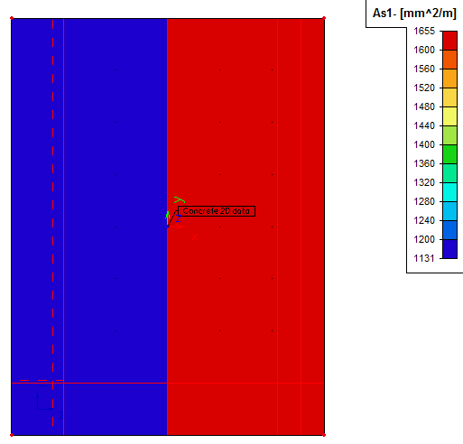
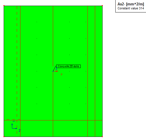
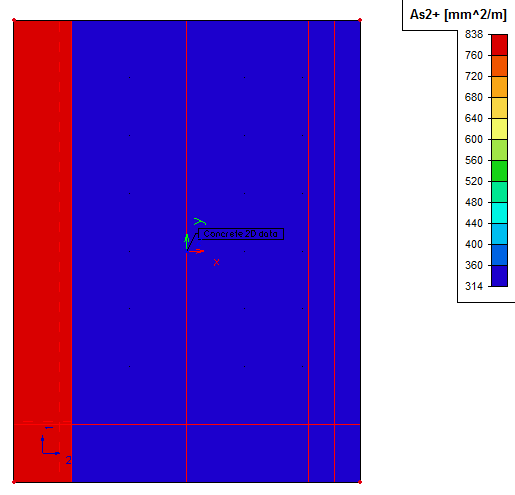
We will also define reinforcement for second direction and also for upper surface. User reinforcement for both surfaces and both directions will satisfy the ULS design only. For information about the input reinforcement see table below:
|
User reinforcement As1- |
User reinforcement As2- |
|
|
|
|
User reinforcement As1+ |
User reinforcement As2+ |
|
|
|
After the reinforcement design of the user reinforcement for ULS state, it is time to define the reinforcement determining the Code dependent deflections. It can be done in Setup dialog in Menu > Setup > Concrete solver. Picture of this dialog is shown in the previous chapter. We will set this parameter to User reinforcement possibility. Then we must run the design once again to regain the amounts of reinforcement.
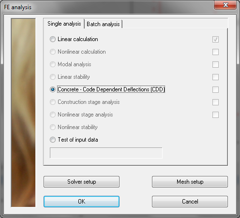
Now if we start the FE analysis dialog, possibility Concrete – Code Dependent Deflections (CDD) is activated and may be chosen. After selection of this option we can proceed to calculation itself by pressing Ok button.
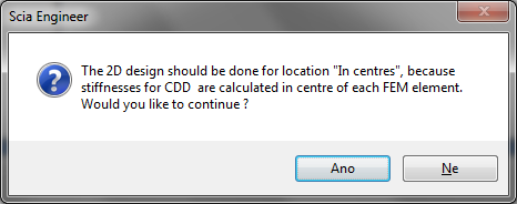
After confirmation of the FE analysis dialog a warning error may appear. This will warn the user about non-consistent location parameter of 2D design.
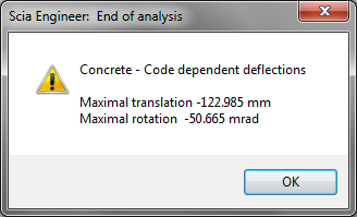
If the user accepts the dialog above, the calculation itself is started and process of determining the deflections should be finished with informational End of analysis dialog. Here maximal values of translation and rotation is displayed.
Now if we go back to the Concrete Advanced service, two new items Stiffness presentation and Deformations, may be found here. They are both under Member check item. See picture below.