Example 2: Flange Induced Buckling
In this second example, the use of a combo-box is illustrated. In addition, the use of Named cells and output parameters with units are explained.
As a practical case, Flange Induced Buckling as specified in article 8 of EN 1993-1-5 is used.
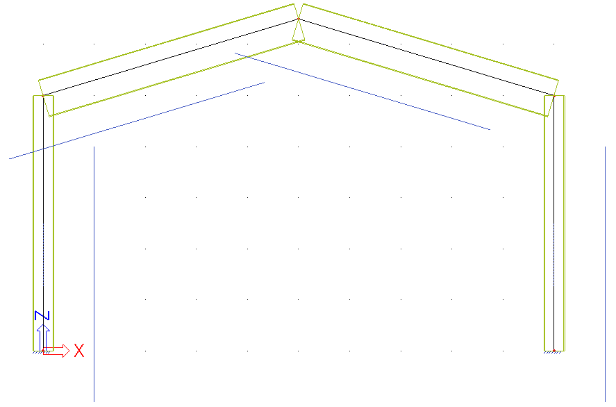
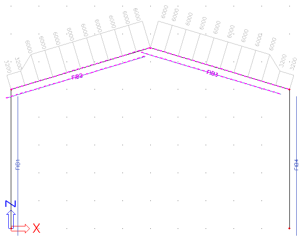
In this example, a frame with rigid supports is modelled. The frame has a column distance of 10m, a column height of 5m and a column top to ridge height of 1,5m. All members are manufactured in S355 according to EC-EN.
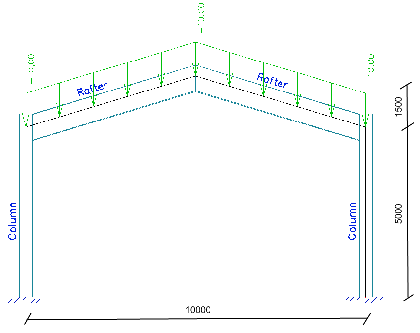
The columns have a sheet welded Iwn cross section with parameters (400, 12, 300, 12, 200, 16). The rafters have a sheet welded Iwn cross section with parameters (750, 12, 500, 12, 200, 16).
One load case is defined, a uniform line load of 10 kN/m on the rafters.
Flange Induced Buckling as specified in article 8 of EN 1993-1-5 concerns the following:
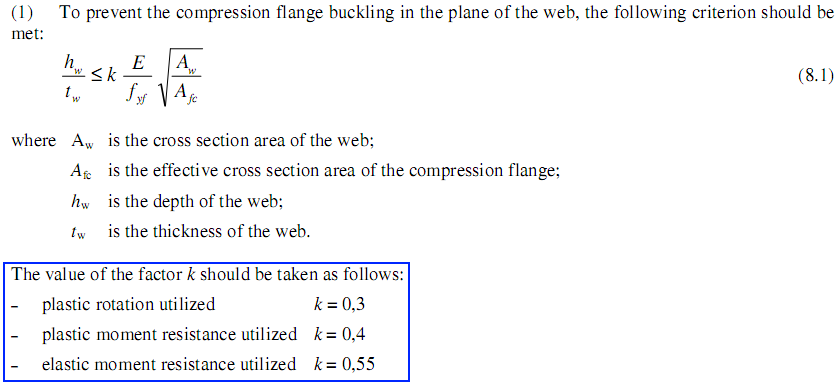
Cross-section and material properties will be sent to Excel. In addition, the factor k will be determined according to a combo-box setting. The combo-box contents are those shown in the blue rectangle of the previous picture.
The check is done using the corresponding Excel file “Excel_Example_2.xls”
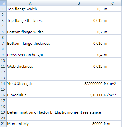
The Excel file contains two worksheets. On the sheet ‘Input’ the input data from SCIA Engineer are set:
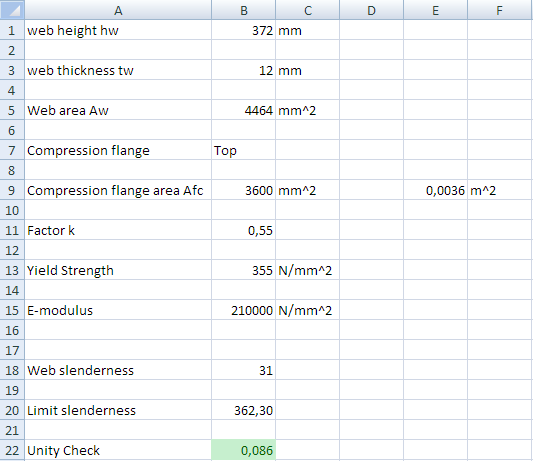
The sheet ‘Check’ shows the intermediate results and the unity check:
Since the check requires the area of the compression flange, the sign of the bending moment is used to determine which flange is in compression at each section along a member.
In the Excel file, all cells to which data has to be mapped and from which data is read have been given a name. This allows for a very easy definition of the mapping since these same names will be available in the mapping dialog of SCIA Engineer.
Step 1: Activate the functionality External Application Checks
The first step is to activate the functionality External application checks on the Functionality tab in the Project Data.
Step 2: Create User Defined Additional Data
In the second step, User Defined Additional Data will be defined.
Through Tools > User defined AddData the User Defined Additional Data Library can be opened.
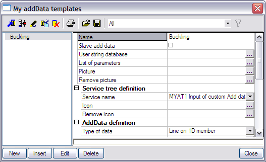
The Name of the additional data is changed to ‘Buckling’.
Step 2.1 Slave data
Only one type of additional data will be defined here and as such the check-box Slave add data is left unchecked.
Step 2.2 Define text strings
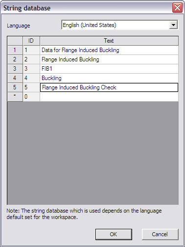
In the User string database the required strings are defined for the definition of the additional data.
Since in this example Flange Induced Buckling is being illustrated the strings are modified as follows:
|
Type for which the string is used |
Default string |
String used in this example |
|---|---|---|
|
Service name |
MYAT1 Input of custom add data |
Data for Flange Induced Buckling |
|
Type name |
MYAT1 Custom defined add data |
Flange Induced Buckling |
|
Short name |
MYAT1 MADI |
FIB1 |
|
Description |
MYAT1 Description |
Buckling |
|
Name of check |
MYAT1 Custom check |
Flange Induced Buckling Check |
The necessary strings for the definition of the data have been inputted and in the next step the parameters can be defined.
Step 2.3 Define parameters
In this example, the mapping will concern of default SCIA Engineer data (Cross-section dimensions, material properties and internal forces) except for the determination of the factor k.
In the code, this parameter was defined as follows:
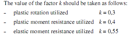
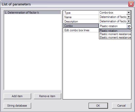
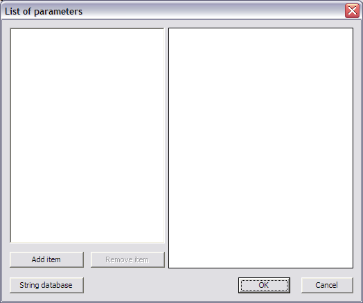
To choose between these options, a combo-box parameter will be defined through List of parameters.

For this example, one parameter will thus be defined:
|
Parameter |
Type |
Combo-box lines |
|---|---|---|
|
Determination of factor k |
Combo-box |
Plastic rotation Plastic moment resistance Elastic moment resistance |
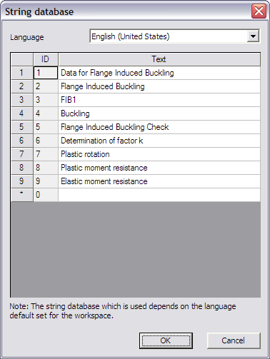
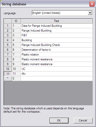
Through the button String database the text string database can be directly accessed. This allows a quick input of the strings required for the parameters.
For this example the following strings are added:
|
Strings used in this example |
|---|
|
Determination of factor k |
|
Plastic rotation |
|
Plastic moment resistance |
|
Elastic moment resistance |
Next, through the button Add item the parameter is added.
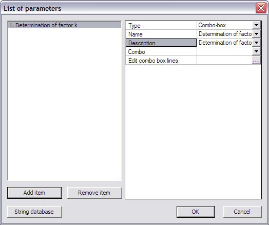
The Type field is set to ‘Combo-box’.
For both the Name and Description fields the string ‘Determination of factor k’ is set.
Next, the lines in the combo-box are defined through the edit button Edit combo box lines.
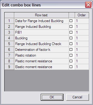
This dialog shows all strings defined in the user string database in the column Row text. The checkboxes can be used to specify which strings should be in the combo-box. For this example, the three final strings are thus activated.
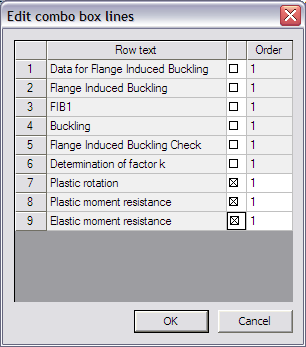
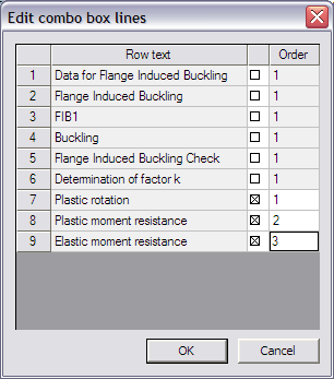
The lines for the combo-box have been defined so the next step is to set the order of the lines in the Order column.
The line with Order number 1 will be the first line in the combo-box. Each next line should have its Order incremented by 1.
For this example, the order in which the strings have been inputted in the string database is kept and thus in the Order column the numbers ‘1’, ‘2’ and ‘3’ are inputted.
When closing this dialog, the Combo item in the List of Parameters dialog shows how the combo-box will look like.
The combo-box parameter has now been defined and the dialog can be closed.
Step 2.4 Add a picture to the Additional Data
To clarify the use of the additional data and the defined parameters a picture can be added using the Picture button.
In this example the picture Excel_Example_2_Picture.bmp will be used.
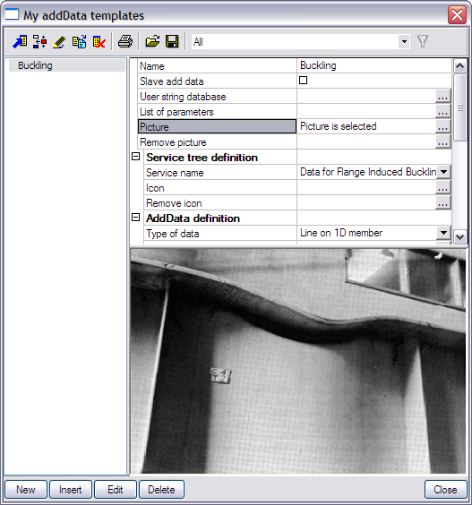
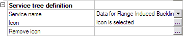
Step 2.5 Define Service Tree
In the next step the Service Tree is defined through the group Service tree definition.
The Service name is taken automatically from the text string database.
To clarify the Service name, an icon can be added using the Icon button.
In this example the icon Excel_Example_2_Icon.bmp will be used.
Step 2.6 Define the Additional Data
Using the data from the previous steps, the additional data can now be defined in the group AddData definition.
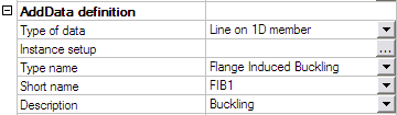
Flange Induced Buckling has to be checked in each section of the member since the check contains the area of the compression flange which can change along the length of the member. Therefore the field Type of data is set to ‘Line on 1D member’.
The Type name, Short name and Description are taken automatically from the text string database.
To get an overview of all the data entered in the previous steps the button Instance Setup is used.
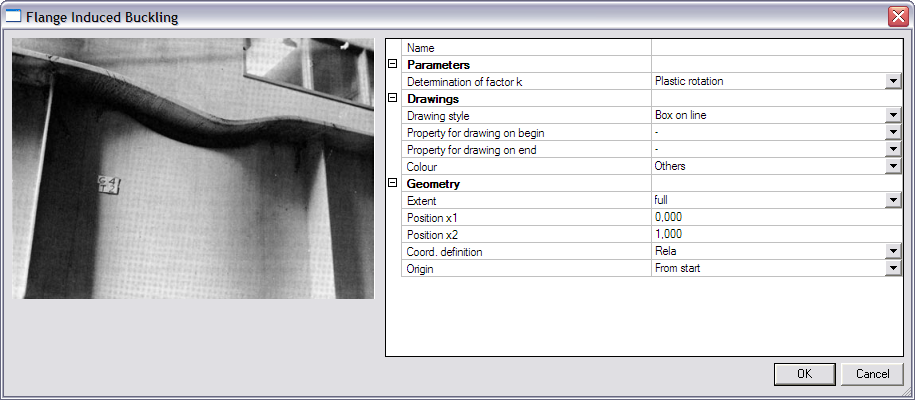
The Parameters group shows the combo-box defined in Step 2.3.
In the Drawings group, the Drawing style is set to ‘Simple’. For the Colour field ‘Water load’ is chosen.
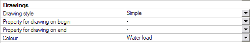
Since in this example no numerical parameter was defined, no Property for drawing on begin/end is specified.
Step 2.7 Define the Check
In the group Check data the necessary data for the check itself can now be defined.
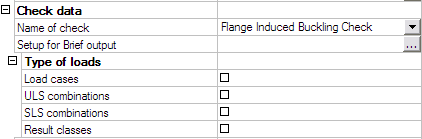
The Name of check is taken automatically from the text string database.
The Type of loads group allows to specify which load types will be available for the check. Only the selected items will be available when executing the check.
Since in this example only one load case was defined, only the option ‘Load cases’ will be activated.

The final item for defining the check is the Setup for Brief output where the output parameters have to be defined.
For this example, two parameters will be defined: the unity check value and the area of the compression flange.
|
Parameter |
Unit |
|---|---|
|
Unity Check UC |
- |
|
Area of compression flange Afc |
mm² |
First of all, through the button String database the text string database is accessed to define the required strings. For this example the following strings are added:
|
Strings used in this example |
|---|
|
UC |
|
Afc |
When the strings are defined, the first parameter is added through the button Add item.
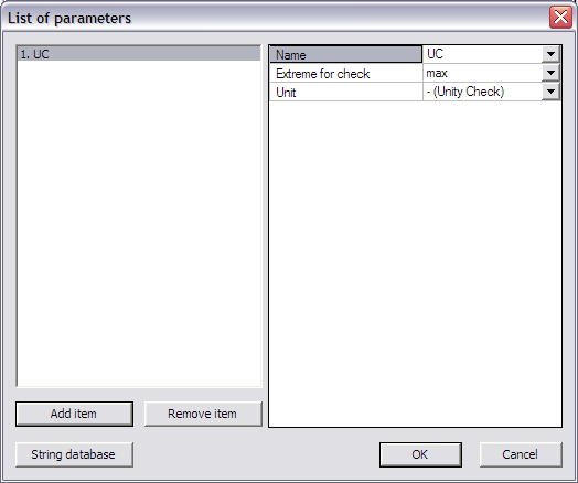
In the Name field the ‘UC’ string is chosen from the string database.
The Extreme for check is left on ‘max’ since the maximal unity check value is extreme in this case.
Since it concerns a unity check, the Unit field is left on ‘– (Unity Check)’.
Again using the button Add item the second parameter is added.
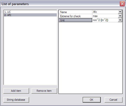
In the Name field the ‘Afc’ string is chosen from the string database.
The Extreme for check is left on ‘max’. For this example it is of no importance if the extreme is minimum or maximum, the purpose of the parameter is to see which flange is in compression.
Since this parameter concerns an area, the Unit field is set to ‘mm^2 ([m^2])’.
During the mapping, parameters are always sent to Excel in basic SI units. Output parameters are also read from Excel in basic SI units. For this example this implies that the area in Excel has to be in m^2 as indicated in the Unit field. This unit will then be converted to mm^2 in SCIA Engineer.
The check and output parameters have now been defined so in the next step the link can be set.
Step 2.8 Specify the type of external link
In the External link data group the Type of external link allows to specify which external application will be used.
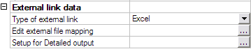
In this example the link is made with Excel and thus ‘Excel’ is chosen.
Step 2.9 Define the mapping with the external application
All preparation has now been done, what remains is the most important step of the process: defining the actual mapping between properties and parameters of SCIA Engineer and the data fields (i.e. Excel cells) of the external application.
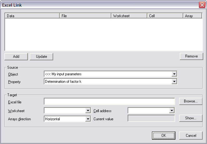
Through the button Edit external file mapping the mapping dialog is opened.
The first time the mapping dialog is opened can take a few seconds. This is because, during the opening, all document tables are refreshed since these properties are available in the mapping dialog. This way, when new items are added to the document in future versions of SCIA Engineer, they will automatically be available in the mapping dialog also.
In this example, the Excel file contains two worksheets. On the sheet ‘Input’ the input data from SCIA Engineer are set:
The sheet ‘Check’ shows the intermediate results and the unity check:
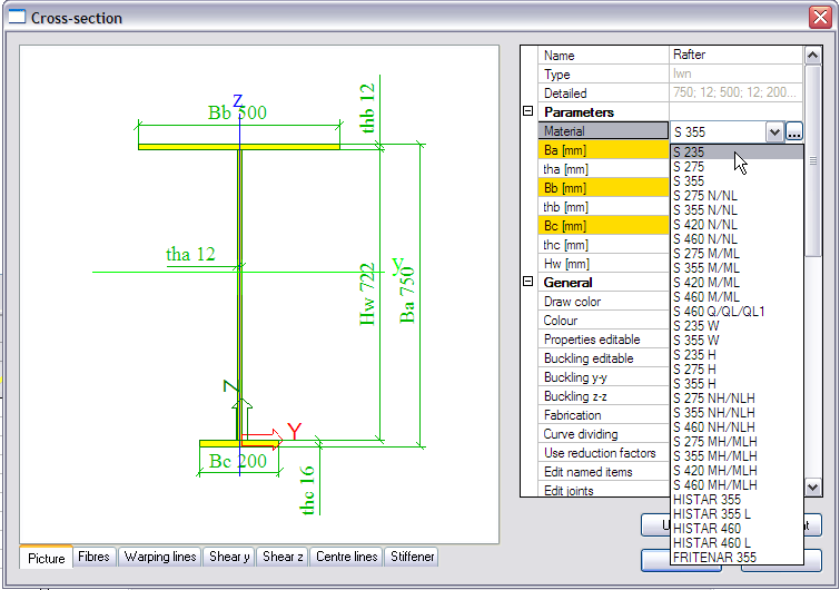
In this example, cross-section properties have to be sent to Excel. In the Cross-section manager, it can be seen how the dimensions of a sheet welded Iwn section are defined:
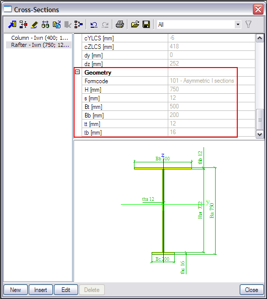
More specifically the properties H, s, Bt, Bb, tt and tb will have to be mapped to Excel.
As specified in the introduction of this example, in the Excel file, all cells to which data has to be mapped and from which data is read have been given a name. These named cells can now be used in the Cell address field instead of manually typing the cell number.
The following table shows which properties should be mapped to which cells:
|
Object |
Property |
Worksheet |
Named Cell (Address) |
|---|---|---|---|
|
Cross-Sections |
Bt (Geometry) |
Input |
Top_flange_width (B1) |
|
Cross-Sections |
tt (Geometry) |
Input |
Top_flange_thickness (B3) |
|
Cross-Sections |
Bb (Geometry) |
Input |
Bottom_flange_width (B5) |
|
Cross-Sections |
tb (Geometry) |
Input |
Bottom_flange_thickness (B7) |
|
Cross-Sections |
H (Geometry) |
Input |
Cross_section_height (B9) |
|
Cross-Sections |
s (Geometry) |
Input |
Web_thickness (B11) |
|
Steel EC3 |
Yield strength (code independent) |
Input |
Yield_Strength (B14) |
|
Steel EC3 |
E modulus (code independent) |
Input |
E_modulus (B16) |
|
<<< My input parameters |
Determination of factor k |
Input |
Determination_of_k (B19) |
|
Internal forces on member |
My |
Input |
Moment_My (B21) |
|
>>> My output parameters |
UC |
Check |
UC (B22) |
|
>>> My output parameters |
Afc |
Check |
Afc (E9) |
As specified, during the mapping, parameters are always sent to Excel in basic SI units. Output parameters are also read from Excel in basic SI units. Therefore the cell E9 on the Check worksheet in Excel shows the area of the compression flange in SI units.
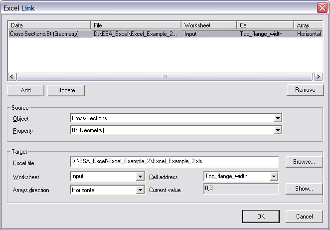
The mapping of the first property, the width of the top flange Bt is thus done as follows:
The Object field is set to ‘Cross-sections’.
In the Property field ‘Bt’ can then be chosen.
Using the Browse button, the file Excel_Example_2.xls is searched.
After the file has been specified, the Worksheet field contains a list of all sheets. This field is set to ‘Input’.
The Arrays direction is set to ‘Horizontal’. In this example no array properties are mapped so choosing ‘Horizontal’ or ‘Vertical’ would make no difference.
Finally, in the field Cell address, using the combo-box the named cell ‘Top_flange_width’ is chosen. Automatically the Current value field will show the current content of the cell, in this case 0,3.
When all input has been done, this mapping is added to the table using the Add button.
In the same way, all other parameters can be mapped using the above table. For all parameters the Arrays direction is set to ‘Horizontal’.

All parameters are now mapped to Excel. The final step left for the definition of the additional data is specifying a Detailed output.
Step 2.10 Define the Detailed output
In Step 2.7 the parameters for the Brief output have been defined. These parameters will be used for the check. In addition, a Detailed output can also be specified to show an in-depth overview of the check.
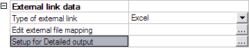
By clicking on Setup for Detailed output, the Detailed output dialog is opened.

In this example, the range will be defined from the cell A1 to the cell C22 on the ‘Check’ worksheet.
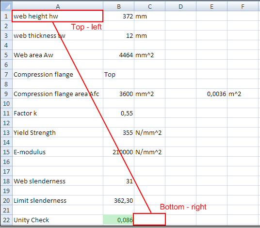
For ease of reference, here also Named cells have been defined in the Excel file.
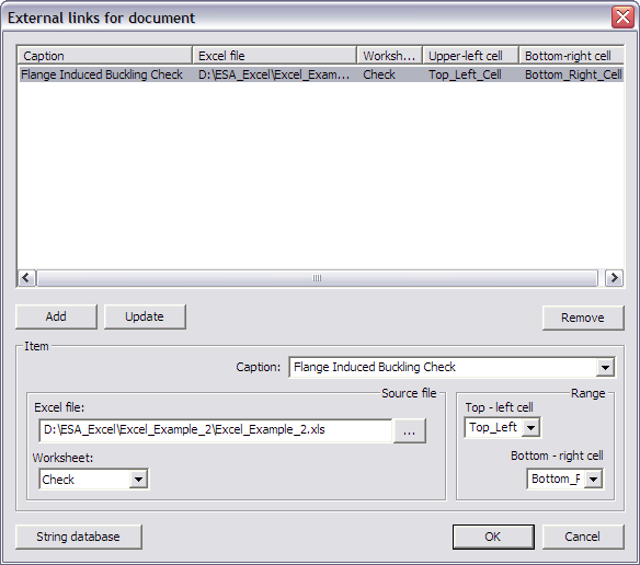
In the Caption field the string ‘Flange Induced Buckling Check’ is chosen.
In the Excel file field the file Excel_Example_2.xls is searched using the browse button.
The Worksheet field is set to ‘Check’.
In the Range group the Top - left cell is set to ‘Top_Left_Cell’ and the Bottom - right cell to ‘Bottom_Right_Cell’.
When all input has been done, the data is added to the table using the Add button.
With this final step, the User Defined Additional Data has been fully inputted and the User Defined Additional Data Library can be closed.
Step 3: Input the User Defined Additional Data on members/nodes
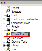
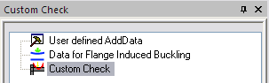
After closing the User Defined Additional Data Library a new service will be shown in the SCIA Engineer tree: Custom Check.
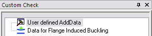
The additional data which was defined in Step 2, can now be inputted on the member. When double clicking on Data for Flange Induced Buckling the dialog with the properties of the data is displayed:
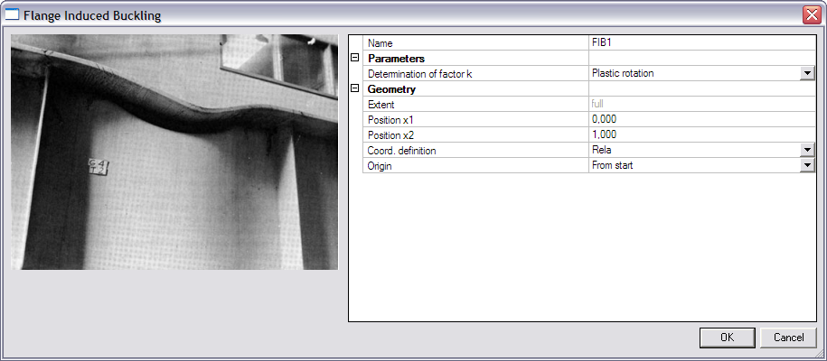
The Parameters group holds the user defined parameters of Step 2.3 with their default values. In this case the combo-box ‘Determination of factor k’.
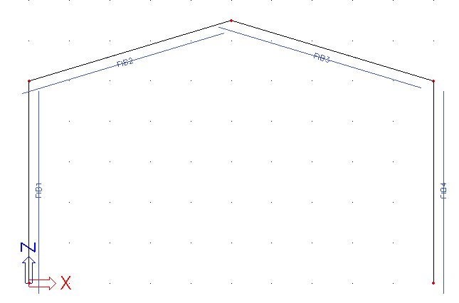
The default values of the dialog are confirmed with [OK] and the data is inputted on all members.
Using the default SCIA Engineer view parameters, the name of the additional data can be displayed.
The data has now been inputted and in the next step the check can be executed.
Step 4: Execute the Custom Check
In Step 2 the additional data has been defined including the definition of the check, the mapping to Excel… In Step 3 the additional data has been inputted. What is left is the execution of the check.
First of all the linear analysis is launched since internal forces will have to be sent to Excel.

When user defined additional data was inputted and the analysis has been executed, the Custom Check service will show a new item: Custom Check.
The default check service property window accompanies this check:
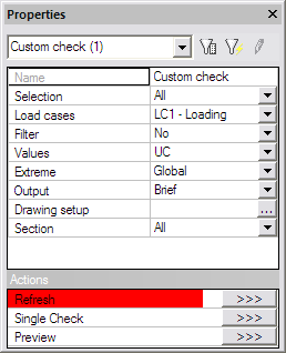
The Refresh action button is pressed to execute the check. The following check result is shown on screen:
The asymmetric result for the columns is correct since different flanges are in compression on both column sides.
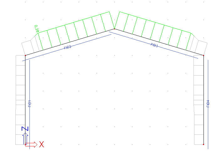
This can be checked by reviewing the compression flange area:
The Values field is changed to ‘Afc’.
The Extreme field is changed to ‘Section’ to see the results in each section.

After pressing the Refresh action button the following result is shown on screen:
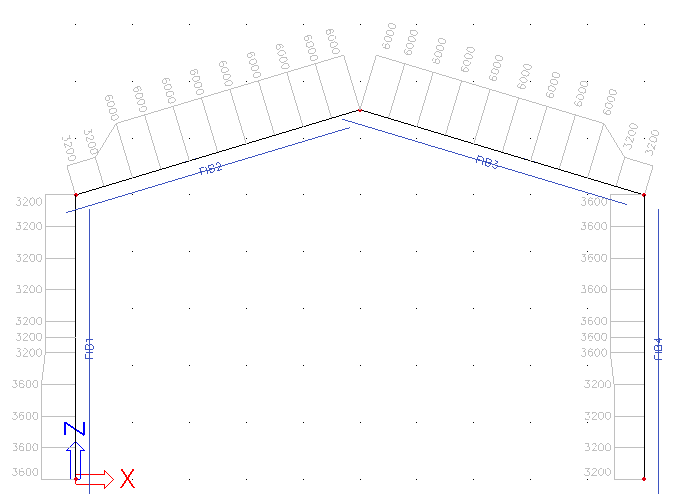
In order to see only the results for the rafters, the Selection field is set to ‘Current’. This implies a selection has to be made which in this case implies the additional data of the rafters and not the members themselves!
The external application check is based on user defined additional data. The check is performed for the members/nodes on which this user defined additional data has been defined. Therefore this additional data has to be selected and not the member or node as in other checks.
After pressing the Refresh action button the following result is shown on screen:
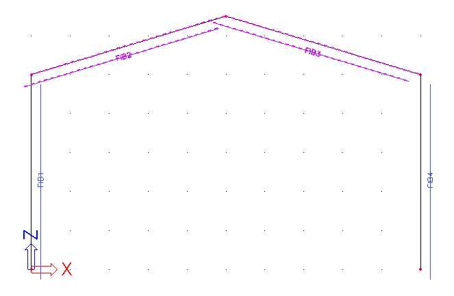
Next, the Values field is changed back to ‘UC’ and the Extreme field is set to ‘Member’.
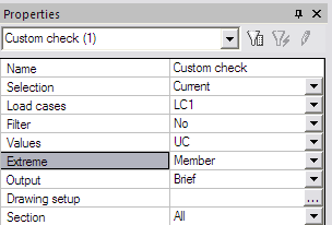
After pressing the Refresh action button the following result is shown on screen:

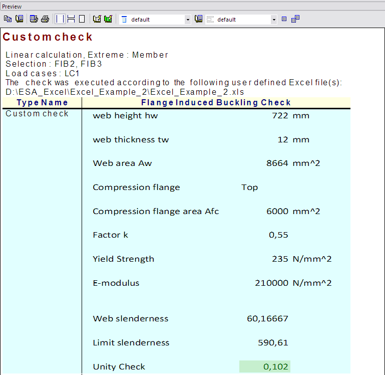
When pressing the Preview action button, the Brief preview shows the following:
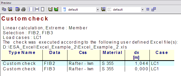
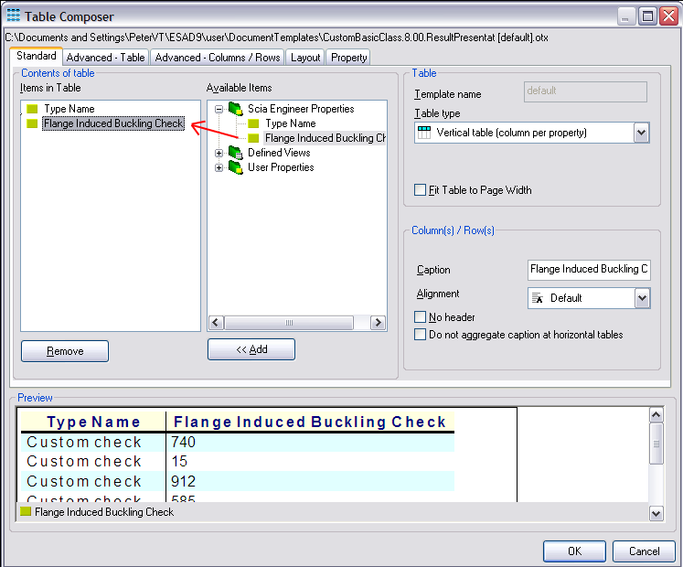
Using the tablecomposer, both the UC and Afc parameters can be added to the output:
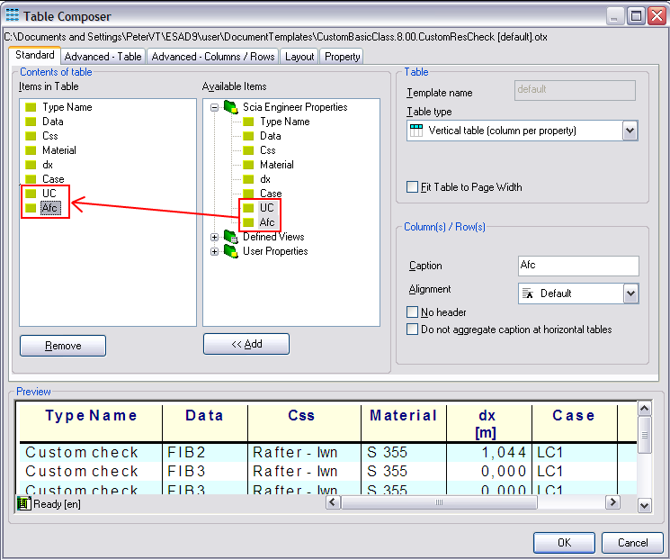
When pressing the Preview action button, the Brief preview now shows the following:
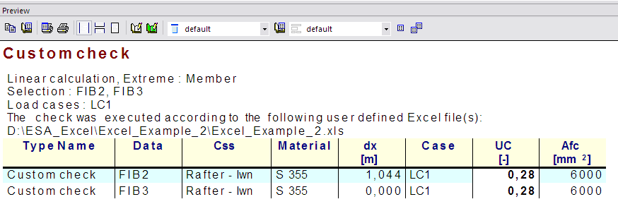
Note the Afc parameter which is shown with the unit defined in step 2.7.
The result was obtained by using the default setting for the factor k: ‘Plastic rotation’.
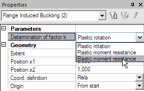
Since both additional data on the beams are selected, their properties can be modified in the Property window. In this example, the Determination of factor k is changed to ‘Elastic moment resistance’.
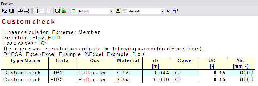
After pressing the Refresh action button, this less severe unity check is shown:
Finally, the Detailed output is examined. The Output field is set to ‘Detailed’ and the Refresh action button is pressed.
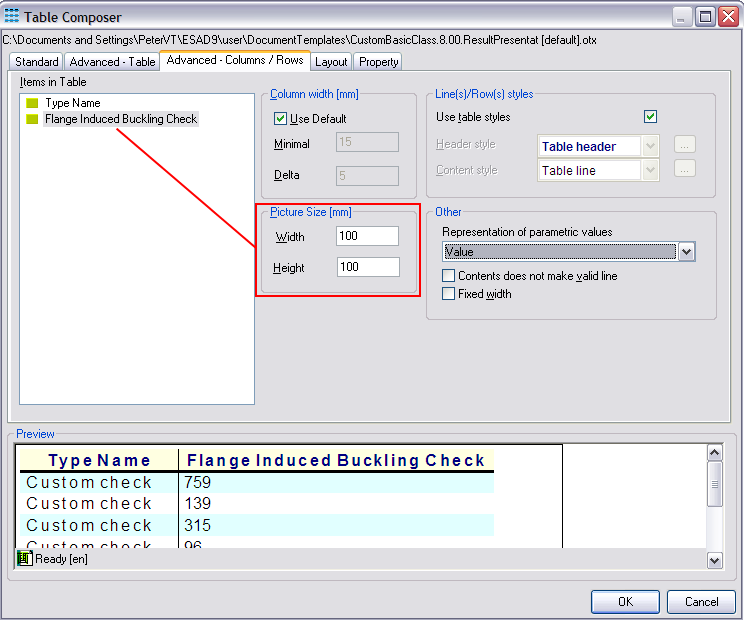
Through the table composer the Flange Induced Buckling Check item can be added and its picture size set to 100mm by 100mm:
This gives the following output after refreshing:
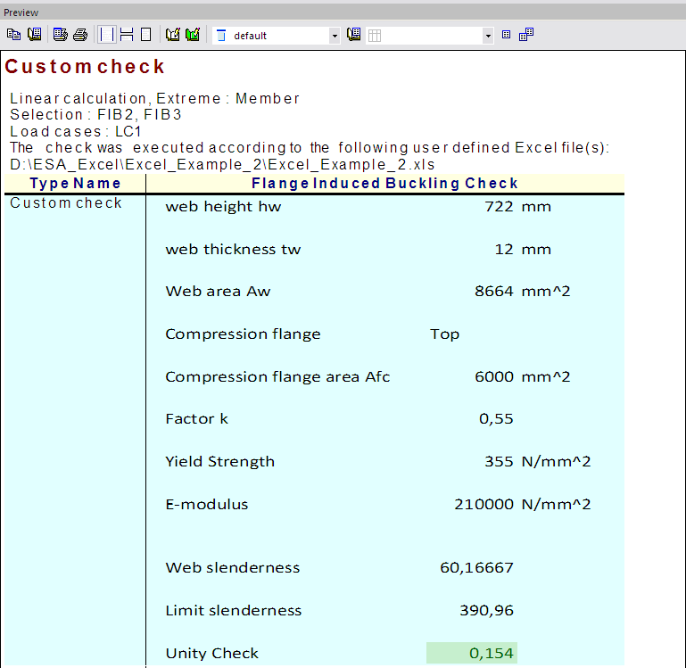
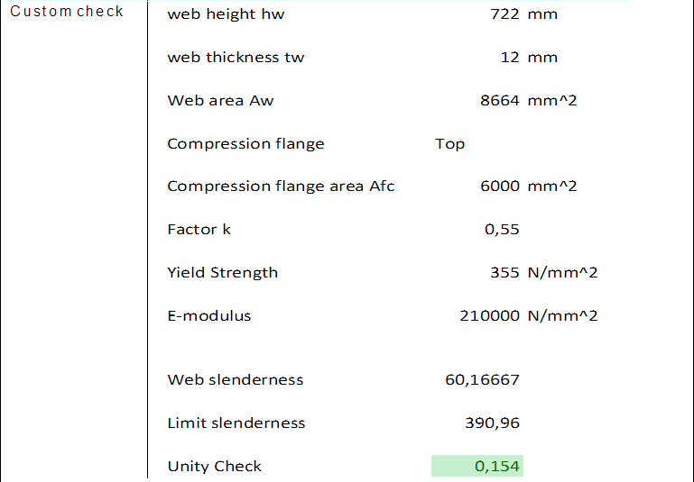
Two outputs are given since the extreme per member was asked (with two entities selected). The Excel file could be modified to show also the name of the member and the section position on the output.
To finalize this example, the material for the rafter members is changed from S355 to S235:
After recalculating, the Detailed output for the rafter members is refreshed:
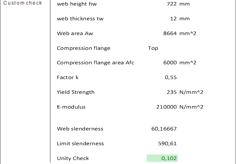
The output clearly shows that the change of material is correctly taken into account.
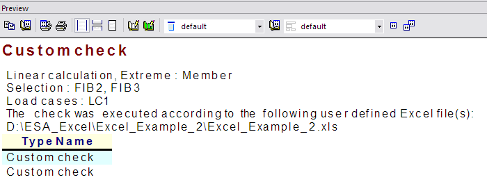
The check has now been executed and reviewed. To end this step, the document of SCIA Engineer is examined.
In the document, the inputted User defined additional data can be inserted into the document in the same way as any other default additional data.
In the New document item dialog, the Special chapter holds the tables for all user defined additional data.
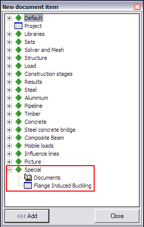
In this example Flange Induced Buckling was defined and thus this data can be added into the document.
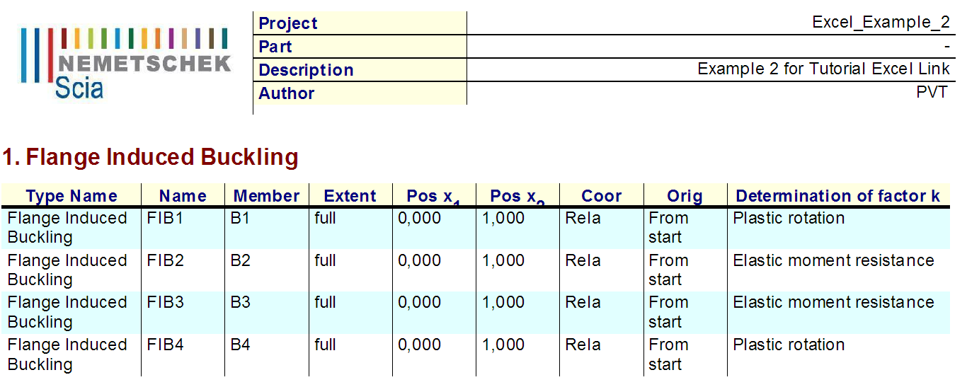
The table shows the different properties of the additional data, including the user defined parameter ‘Determination of factor k’. In the same way as for any other default additional data of SCIA Engineer this table can be edited and modified through the Table Composer.
Through the Active Document feature of SCIA Engineer, the user define properties can also be edited inside the document.
Step 5: Save the User Defined Additional Data into a database for future use
If required, this additional data can be saved into a database for future use as illustrated in Example 1.