7.3 Internal forces for 2D members (plate, wall)
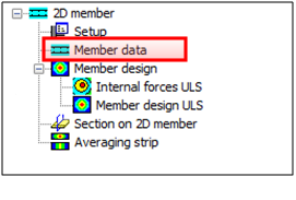
In advance of design process itself, it might be useful to check inner forces, which will enter the design. It is possible to do so in Inner forces ULS service in Concrete > 2D Member > Member design > Internal forces ULS.
In this service are presented these types of inner forces, which might be changed through the attribute Type value:
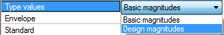
- Basic magnitudes (inner forces directly from FEM analysis, presented in local coordinate system of appropriate 2D member)
- Design magnitudes (design forces in reinforcement, calculated for reinforcement directions and design force in concrete compression strut)
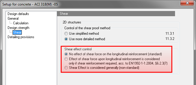
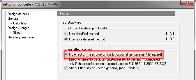
As mentioned above, dimensional magnitudes are recalculated into reinforcement directions, moreover in these values is torsion moment mxy also taken into a count. It is also possible to calculate with influence of tension force caused by shear stress. This can be set in Concrete setup dialog with attribute Shear effect control 6.2.3(7), under Concrete > ULS > Shear > 2D structures (see chapter "4.2 Concrete setup for 2D members"). This attribute is possible to set three ways:
- No effect of shear force on the longitudinal reinforcement (tension force from shear stress will not be considered in design forces calculation)
- Effect of shear force upon longitudinal reinforcement is considered in SR2 (tension force from shear stress will be considered in design forces calculation only on elements, where shear force is not covered by concrete capacity, i.e. on elements, where shear reinforcement is needed)
- Shear effect considered generally (tension force from shear stress will be considered in design forces calculation on all elements, nevertheless the shear reinforcement is, or is not needed)
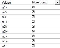
Values, which will be available in value list for Type values attribute set to Design magnitudes depend on:
- Type of the structure set during definition of the project itself. For 2D members project is possible to set three options, Plate XY, Wall XY and general XYZ.
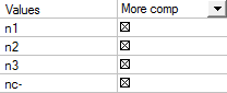
- Layers in the centre attribute placed in 2D concrete data. If all 2D members in the project have 2D concrete member data defined with attribute Layers in the centre active, then only n1-, n2-, nc- values will be displayed the list of values in General XYZ project.
- Number of reinforcement directions. If all 2D members have only 2 reinforcement direction defined, then values with index 3 will not be displayed in the list of values.
|
Plate XY |
Wall XY |
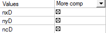
General XYZ |
|---|---|---|
|
|
|
|
Description of the values above:
|
m1-,m2-,m3-,m1+,m2+,m3+ |
Design bending moment in reinforcement direction 1,2 and 3 for lower surface (-) or upper surface (+). These values are used for reinforcement design.
|
|
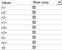
n1-,n2-,n3-,n1+,n2+,n3+ |
Design normal force in reinforcement direction 1,2 and 3 for lower surface (-) or upper surface (+). These values are used for reinforcement design.
|
|
n1,n2,n3 |
Design normal force in reinforcement direction 1,2 and 3 placed in the centre of gravity of 2D member. These values are used for reinforcement design.
|
|
mc-, mc+ |
Design bending moment in concrete compression strut for lower surface (-) or upper surface (+), which must be covered by concrete. If the concrete strut is not able to cover this moment, design will end up with error message.
|
|
nc-, nc+ |
Design normal force in concrete compression strut for lower surface (-) or upper surface (+), which must be covered by concrete. If the concrete strut is not able to cover this force, design will end up with error message.
|
|
nc |
Design normal force in concrete compression strut placed in the centre of gravity of 2D member, which must be covered by concrete. If the concrete strut is not able to cover this force, design will end up with error message.
|
|
vd |
Resultant shear force, which takes effect perpendicular to 2D member plane.
|
Upper and lower surface of 2D member is determined by the Z axis direction of local coordinate system (LCS). Upper surface is in the positive direction of the Z axis and on the other hand Lower surface is in negative direction of Z axis. Upper surface values are marked with + and lower values are marked with.
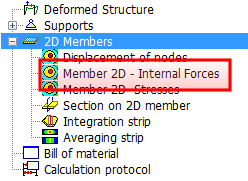
7.3.1 Difference between internal forces in Results and Concrete tree
It is possible to check inner forces also in Results through Member 2D – Internal Forces item. Here, user can also view design magnitudes, if attribute Type of the force is set to Elementary design magnitudes possibility.
Elementary design magnitudes in tree Results are determined differently than in Concrete tree. The difference is that Elementary design forces are reached for X and Y axis of local coordinate system of the 2D member, not for reinforcement directions as it is done for determination of design magnitudes in Concrete tree. In Elementary design forces is also torsion moment mxy taken into a count, however tension force from shear stress is not. These Elementary design forces might be used only for presentation. For design of the amount of reinforcement are Design magnitudes from Concrete tree used.
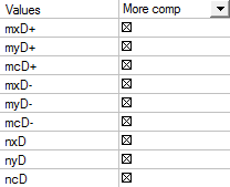
Values displayed in value list, when attribute Type forces is set to Elementary design magnitudes possibility are only dependent to type of the structure set during definition of the project itself. For 2D members project is possible to set three options, Plate XY, Wall XY and general XYZ.
|
Plate XY |
Wall XY |
General XYZ |
|---|---|---|
|
|
|
|
Description of the values above:
|
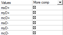
mxD+, mxD- |
Design bending moment in X axis direction of local coordinate system (LCS) for lower surface (-) or upper surface (+).
|
|
myD+, myD+ |
Design bending moment in Y axis direction of local coordinate system (LCS) for lower surface (-) or upper surface (+).
|
|
nxD+, nxD- |
Design normal force in X axis direction of local coordinate system (LCS) for lower surface (-) or upper surface (+).
|
|
nyD+, nyD+ |
Design normal force in Y axis direction of local coordinate system (LCS) for lower surface (-) or upper surface (+).
|
|
mcD+, mcD- |
Design bending moment in concrete compression strut for lower surface (-) or upper surface (+), which must be covered by concrete.
|
|
ncD-, ncD+ |
Design normal force in concrete compression strut for lower surface (-) or upper surface (+), which must be covered by concrete.
|
From what is mentioned above, design inner forces magnitudes, in Concrete tree and Results tree, have same values only when on selected 2D member:
- has only two reinforcement directions defined and are perpendicular to each other
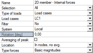
- is first reinforcement direction angle identical with the value of rotation, defined in properties of Member 2D – Internal Forces, in Results tree.
|
Member Data in Concrete tree |
Member 2D - Internal Forces in Results tree |
|---|---|
|
|
|
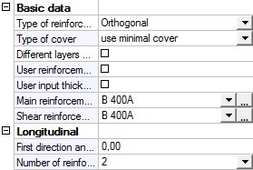
- influence of tension force is not considered for shear reinforcement,. That means that for attribute Shear effect control is set to no shear effect is considered possibility in concrete setup dialog (see chapter "4.2 Concrete setup for 2D members")
Upper and lower surface of 2D member is determined by the Z axis direction of local coordinate system (LCS). Upper surface is in the positive direction of the Z axis and on the other hand Lower surface is in negative direction of Z axis. Upper surface values are marked with + and lower values are marked with.