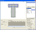
Defining the shape of a new stirrup
The real shape of a stirrup (or several stirrups) in a particular cross-section shape is defined in the dialogue called Stirrup shape.
Graphical window
The graphical window displays the cross-section shape, auxiliary entities and defined stirrups.
|
Shape of the cross-section |
The cross-section shape is drawn and filled with colour. |
|
Edge numbers |
Individual edges are numbered. The numbering is referred to in various dialogues for input and editing of reinforcement. |
|
Offset |
Edges of the cross-section are drawn also with an offset. The offset is in dashed line that can be seen before defined stirrups cover this line. |
|
Characteristic points |
Corner and intersection points may be drawn in the picture as well to simplify manual definition of a new stirrup shape. Also user defined points may be drawn. |
|
Inserted stirrup |
Each defined stirrup is displayed. |
Stirrup
User defined points
|
Add |
If required, the user may insert arbitrary number of "auxiliary" points. It is then possible to pick these points when the shape of a new stirrup is being defined manually. |
|
Delete |
Any of already defined "auxiliary" points can be deleted. |
|
Delete All |
All points may be deleted in one step. |
List of inserted stirrups
|
List of defined stirrups |
The list states all the stirrups defined in the current template. If required, any stirrup may be removed (via button [Delete]). |
Properties of stirrups – analysis model
Other stirrups properties
|
Number of cuts |
Specifies the number of legs of the stirrup. |
|
Diameter of mandrel |
Defines the diameter of stirrup bend. |
Properties of stirrups – structural model
|
Name |
Shows the name of the stirrup. It can be changed on tab Analysis model. |
|
Anchorage type |
Selects the anchorage type. See Hooks for options. If torsion is switched on in "Analysis model" parameters, the user may select from three types of stirrup (marked A, B, C). If torsion is switched off in "Analysis model" parameters, two other types of stirrup are available (D, E). |
|
Vertex |
Selects the vertex at which the anchoring detail is made. |
|
"dimensions" |
Defines the anchorage length. The exact meaning of the parameter is clear from the guiding picture. In order to see the picture, position the mouse cursor on top of words Anchorage type and let the mouse steady for a while. The picture is shown. |
|
Keep formwork |
If this option is ON, the program verifies the anchorage length and if the hook would stick out of the formwork, an additional bend is added so that the hook follows the shape of the formwork (i.e. the outline of the cross-section). |
|
Permanent code check |
The total anchorage length is permanently checked to satisfy the condition of the minimal length stipulated in the appropriate standard. That means that e.g. change of the diameter of the bar may result in the change of the anchorage length. |
|
Total bar length |
Shows the total bar length. |
|
Set to code |
The anchorage length is adjusted in accordance with the active standard. The minimum anchorage length is calculated and the hook length is adjusted accordingly. Normally, only the minimal length is checked, i.e. it is not possible to input a stirrup with anchorage length shorter than the minimum. However, it is possible to define larger anchorage length. This button should re-adjust the minimum required anchorage length. |
|
Load default |
Reads the default values. |
Picture properties
|
Draw intersection points |
If ON, points in intersections of individual "offset edges" are drawn in the graphical window. This option is available only for cross-section shapes where this "intersection" exists. For example, for rectangle this option is not available. |
|
Draw corner points |
If ON, points in corners of the "offset outline" of the cross-section are drawn in the graphical window. |
|
Defines the size of the auxiliary points and text. |
|
|
Draw dimensions |
If ON, dimension lines are displayed in the graphical window of the dialogue. |
|
Redraw |
If necessary, the graphical window may be manually regenerated. |
The procedure to define an automatic stirrup
-
Follow the procedure given in chapter Creating a new shear reinforcement template and open the Stirrup shape dialogue.
-
Click button [Automatic] (Note that this button may not be accessible for every cross-section shape).
-
A new stirrup following the shape of the cross-section is added to the template.
-
If necessary, edit stirrup properties in the property table at the right hand side of the table.
The procedure to define user-defined auxiliary points
-
Follow the procedure given in chapter Creating a new shear reinforcement template and open the Stirrup shape dialogue.
-
Click button [Add].
-
A new point is added to the list of points.
-
Select the edge and fill in other point parameters.
-
The point appears in the graphical window.
The procedure to input a new stirrup manually
-
Follow the procedure given in chapter Creating a new shear reinforcement template and open the Stirrup shape dialogue.
-
Click button [New stirrup].
-
Pick individual auxiliary points that are supposed to form corners of the stirrup.
-
Close the stirrup or press button [End stirrup] to complete the definition.
-
If necessary, edit stirrup properties in the property table at the right hand side of the dialogue.
Note: In case of Construction stages calculation, the user may select the phase when the stirrup starts to act.

