Specifying sectional parameters and properties
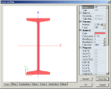
The specification of cross-section parameters can be done in a dialogue for editing of a particular cross-section. This dialogue is opened automatically once the user selects and confirms the required type in the New cross-section type dialogue. In addition, the editing dialogue can be opened any time later via the [Edit] button of the Cross-section manager.
The editing dialogue consists of three main parts:
|
Graphical window |
It displays the cross-section including dimension lines, labels, etc. |
|
Property table |
If comprises all the parameters and sectional characteristics of the cross-section and provides for their editing. |
|
Control buttons |
They perform various tasks connected with the editing. |
Graphical window
The graphical window displays the cross-section, dimension lines, labels and, if available, some of the cross-section properties or characteristics: for example cross-section vertex numbers, shape of stiffeners, diagrams of selected quantities such as shear stress distribution, etc. These additional data about the cross-section are shown on separate tabs (one tab per each property).
Property table
The property table contains all the available and computable cross-section characteristics and parameters. Here the parameters can be input or edited.
The parameters can be divided into three groups: basic sectional characteristics, parameters independent of the cross-section type and type-specific parameters.
It should be stated here that some of the parameters (basic sectional characteristics in particular) cannot be neither input nor edited as they are uniquely determined by the shape and dimensions of the cross-section and are therefore automatically calculated by the program.
There exists a special interconnection between the property table and graphical window that will be described later in this chapter.
Control buttons
Button [Update]
This button starts an algorithm that recalculates the sectional characteristics on the basis of input values.
On entering the editing dialogue for a new cross-section, the property table shows only those parameters that may be edited. In order to see also the computer sectional characteristics, the button must be user.
What’s more, the computed sectional characteristics listed in the property table disappear once the user changes any of the input values. The characteristics are displayed again after this button is pressed. It must be also used to initiate the regeneration of some of the drawings in the graphical window.
Button [Document]
This button invokes the preview window to show the cross-section parameters in a document-style table. The table may be edited the same way as a standard document table.
Button [OK]
This button closes the dialogue and accepts all the inputs and changes made in it.
If a new cross-section has been defined in the editing dialogue it is inserted into the project.
If an existing cross-section has been modified here, the changes are taken into account and saved into the project.
Button [Cancel]
This button closes the dialogue and all the inputs and changes made in it are abandoned.
If a new cross-section has been defined in the editing dialogue it is NOT inserted into the project.
If an existing cross-section has been modified here, the changes are not taken into account and the project remains unchanged.
Graphical window versus property table relation
The graphical window and the property table are provided with a special interlink that provides for easy and lucid style of editing.
The graphical window contains two types of labelling symbols: either dimension lines, or labels, or both. The dimension lines describe dimensions of the individual cross-section edges and parts. The labels depict partial units (e.g. individual rolled steel sections) of a built-up or composite cross-section.
The same items (partial units or dimensions) that are referred to in the graphical window by means of dimension lines and labels can also be found in the property table where they form individual editable cells. In order to facilitate the editing process, there is a link between corresponding property table cells and graphical symbols in the graphical window. That means that if the user wants to change a dimension of a cross-section, it may either (i) select the appropriate cell in the table, or (ii) select the corresponding graphical symbol in the graphical window. What’s more, in order to find quickly which dimension or partial unit the individual table cells refers to, the user can simply select the cell in the table and the appropriate dimension line or label is highlighted in the graphical window.

