Import into the graphical window
Procedure for the import of DWG, DXF or VRML file into the graphical window
-
Start the tree menu function Structure > Drawing tools > Import DWG, DXF, VRML 97file.
-
The Open file dialogue is opened on the screen.
-
Browse for the file and confirm.
-
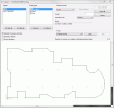
A special import dialogue is opened on the screen.
-
Adjust the required parameters in dialogue and perform the import itself – see below.
Layers
This list box contains the layers that were defined in the original DWG/DXF file. Only selected layers are shown in the preview window of the Import dialogue.
Entity types
This list contains available entity types. Only selected types are shown in the preview window of the Import dialogue.
Selection mode
|
Lines |
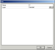
The drawing is read as lines. The lines may be assigned to particular layers. On pressing the "Import" button, the property dialogue is opened and you may specify the required parameters. |
|
Beams |
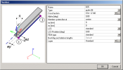
The drawing is read as 1D members. On pressing the "Import" button, the property dialogue is opened and you may specify the required parameters. |
|
Slabs |
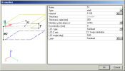
The drawing is read as slabs. On pressing the "Import" button, the property dialogue is opened and you may specify the required parameters. |
|
Solids |
The drawing is read as solid objects that are displayed together with the analysed structure but are neglected during the calculation. |
Note: When slabs are to be imported, it is required that the closed polygon was created already in the file that will be imported.
Scale
The scale for the import. It may be necessary when the drawing is not in SI units. The item provides for the transformation from "imaginary" units of the DWG/DXF file and metres (used in SCIA Engineer as the basic unit).
Note: If the scale is set to 1 (one), SCIA Engineer assumes the data to be stored in metres.
Insertion point
The user can define the insertion point:
Centre
The centre of the model in the imported file is selected as the insertion point (where the cursor is) and by this point the user can place the imported model into the graphical window.
The "centre" is the centre of a bounding rectangle circumscribed around the imported model.
Original
The original insertion point of the imported model is selected as the insertion point (where the cursor is) and by this point the user can place the imported model into the graphical window.
Origin in 0,0,0
The origin of the coordinate system of the imported file is placed into the origin (0,0,0) of the coordinate system in SCIA Engineer.
Sizes
This is an informative item, which shows the dimensions calculated from the input scale.
Tools (Connect curves, Connect solids, Solids smoothing)
These tools allow the user to slightly "modify" the DWG/DXF file before it is imported into SCIA Engineer.
Connect curves
This tool connects individual lines from the imported file to a polyline. This may be useful to reduce the total number of lines in the imported model. It may also simplify the manipulation with the imported model.
The procedure:
-
Select Connect curves.
-
Click [Start].
-
Select the lines to be connected together.
-
Press [Run].
-
Repeat as many times as required.
-
Click [End]
Connect solids
This tool connects individual solids from the imported file. Similarly to connecting of lines (above) it can reduce the total number of solids in the imported model and simplify the manipulation with the imported model.
The procedure:
-
Select Connect solids.
-
Click [Start].
-
Select the solids to be connected together.
-
Press [Run].
-
Repeat as many times as required.
-
Click [End]
Solids smoothing
This tool allows the user to "improve" the imported solid by smoothing the surface, which means reducing the number of edges. This is especially useful if the imported solid was not modelled in an ideal way and contains redundant edges that are not important for the description of the proper shape of the solid.
The procedure:
-
Select Solids smoothing.
-
Click [Start].
-
Select the part of the imported solid that is to be smoothened. Alternatively, use the window selection to select everything (click in the top left corner of the preview window and drag the mouse to the bottom right corner, then release the button).
-
Press [Run] andspecify the smoothness parameter: 0 = the minimum possible number of edges will be used to represent the shape of the imported solid (in some situations it may degrade the shape - e,g, a cube may get rounded corners). 60 = all the edges in the imported model will be preserved. Usually, a few (trial and error) rounds are necessary to find the best value for a particular model - there is no general rule to say which value is the best.
-
Repeat as many times as required.
-
Click [End]
Number of vertexes on polyline substituting imported spline
Some CAD applications use a definition of a spline curve that is different from the one used in SCIA Engineer. Such splines are imported as polylines. This parameter specifies the number of vertexes on the substituting polyline.
Preview window
The view in the preview can be adjusted using the standard SCIA Engineer mouse+key controls (shifted, rotated, zoomed in/out).
Three check boxes are related to the preview window:
OpenGL in preview window
If ON, the parts of the model hidden behind other parts of the model are not drawn. Of OFF, the visibility is not considered and everything is displayed (which means faster response but may cause in some confusions).
OpenGL selection
If ON, the cursor selects the "visible" (the top most) part of the model (if two entities re located over each other). If OFF, the standard selection mode is active.
Show all objects
Some objects from the DWG/DXF that has no equivalent in SCIA Engineer (e.g. text) cannot be imported to SCIA Engineer. This objects are not shown in the Preview window. If you want to see them, select this option.
Note:
Sometimes it may be convenient to import the drawing as lines and only
later (i.e. in SCIA Engineer graphical environment) transform the lines
to 1D members using function Drawing a member in mode Select line (![]() ).
).
Import selected / Import all
This button start the import itself. Either entities selected in the Preview window or All entities from the Preview window are imported as lines or 1D members or slabs (depending on the adjustment of other import parameters). When the button is pressed, the property dialogue for lines or 1D members or slabs (depending on the adjustment of other import parameters) is opened on the screen and you may set the required properties.

